Scanning probe with constant scanning speed

a scanning probe and constant technology, applied in the direction of mechanical roughness/irregularity measurement, measurement devices, instruments, etc., can solve the problems of affecting the accuracy of the measurement process, the relative slowness of the scanning complex form, and the acceleration and deceleration of the machine can introduce inaccuracy in the measurement process, so as to reduce the overheating, improve the lifetime of the probe, and improve the accuracy

Active Publication Date: 2010-01-19
HEXAGON METROLOGY A B (SE)
View PDF13 Cites 21 Cited by
  • Summary
  • Abstract
  • Description
  • Claims
  • Application Information

AI Technical Summary

Benefits of technology

[0015]This invention fulfils the need in the measuring field of a scanning apparatus that can scan all types of surfaces efficiently, e.g. through oscillatory movements, while maintaining a very accurate precision during the whole measurement process, possibly over the whole scanning path. The feature of a constant scanning speed also improves the lifetime of the probes by reducing the overheating due to greater friction forces in acceleration phases.
[0016]Another benefit of the disclosed scanning apparatus is a simple sampling process in order to provide an even distribution of discrete points whose coordinates need to be measured on a surface along the scanning path. Indeed the points will be equally spread along the scanning path by simply setting regular time intervals for the sampling.

Problems solved by technology

One major drawback of these methods known from the art is that they are relatively slow for scanning complex forms, since the whole machine needs to be moved backwards and forwards while covering the whole scanning area of the surface.
Furthermore, the accelerations and decelerations of the machine can introduce inaccuracies in the measurement process because of the strong inertia forces due to the large mass of the pieces in charge of positioning the surface detecting device.
As a result, elastic deformations induced by inertia forces can affect negatively the measures.
These scanning apparatus are yet not suited for non rectilinear movements.
Such scanning methods are, in contrast, very well suited for surfaces with spherical or cylindrical forms, but not for plane surfaces.
However, this apparatus does not take into account cinematic effects to evaluate the deflecting forces applied on the probe, so that the precision is not optimal.

Method used


Image

  • Scanning probe with constant scanning speed
  • Scanning probe with constant scanning speed
  • Scanning probe with constant scanning speed

Examples


Embodiment Construction

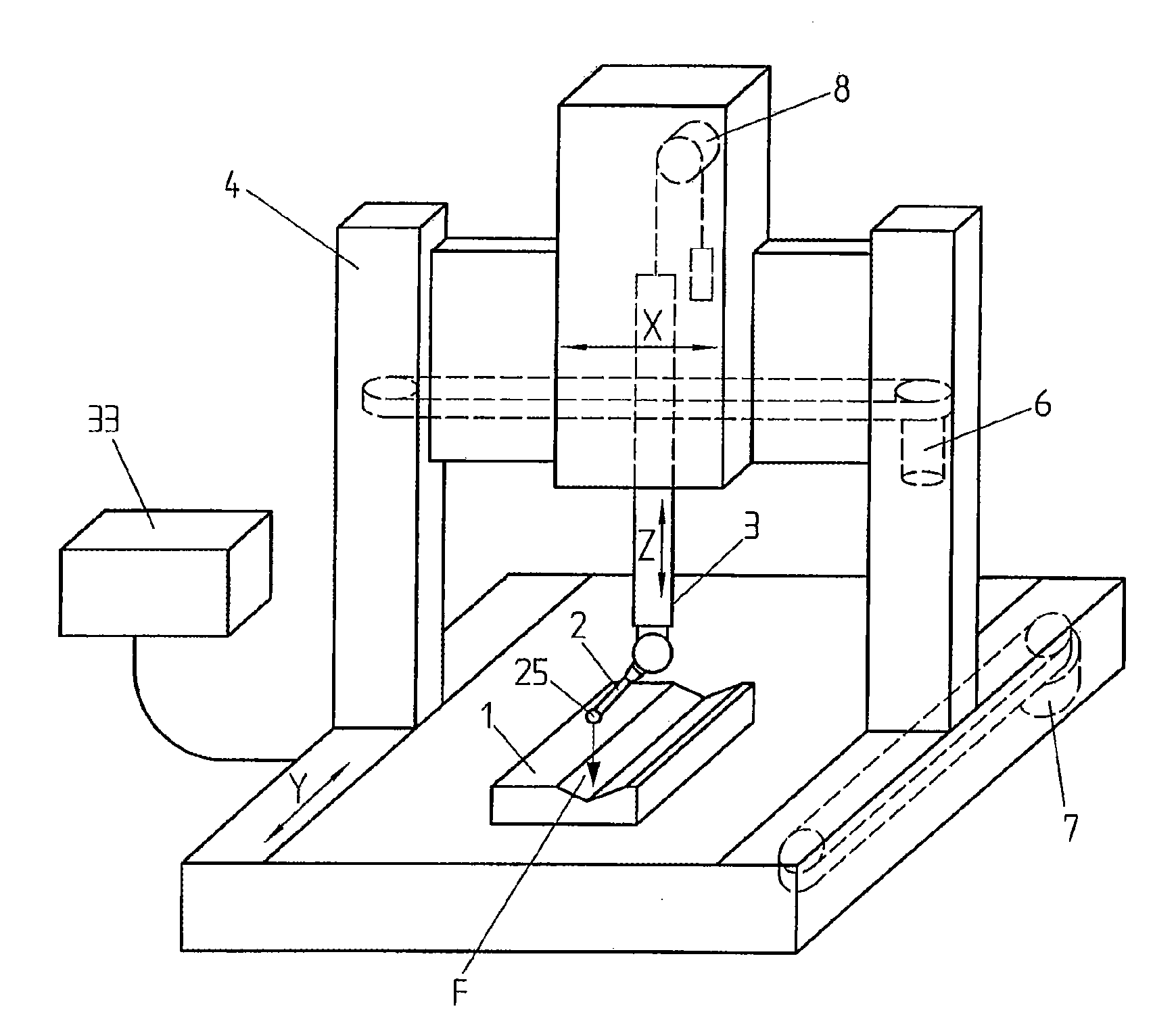
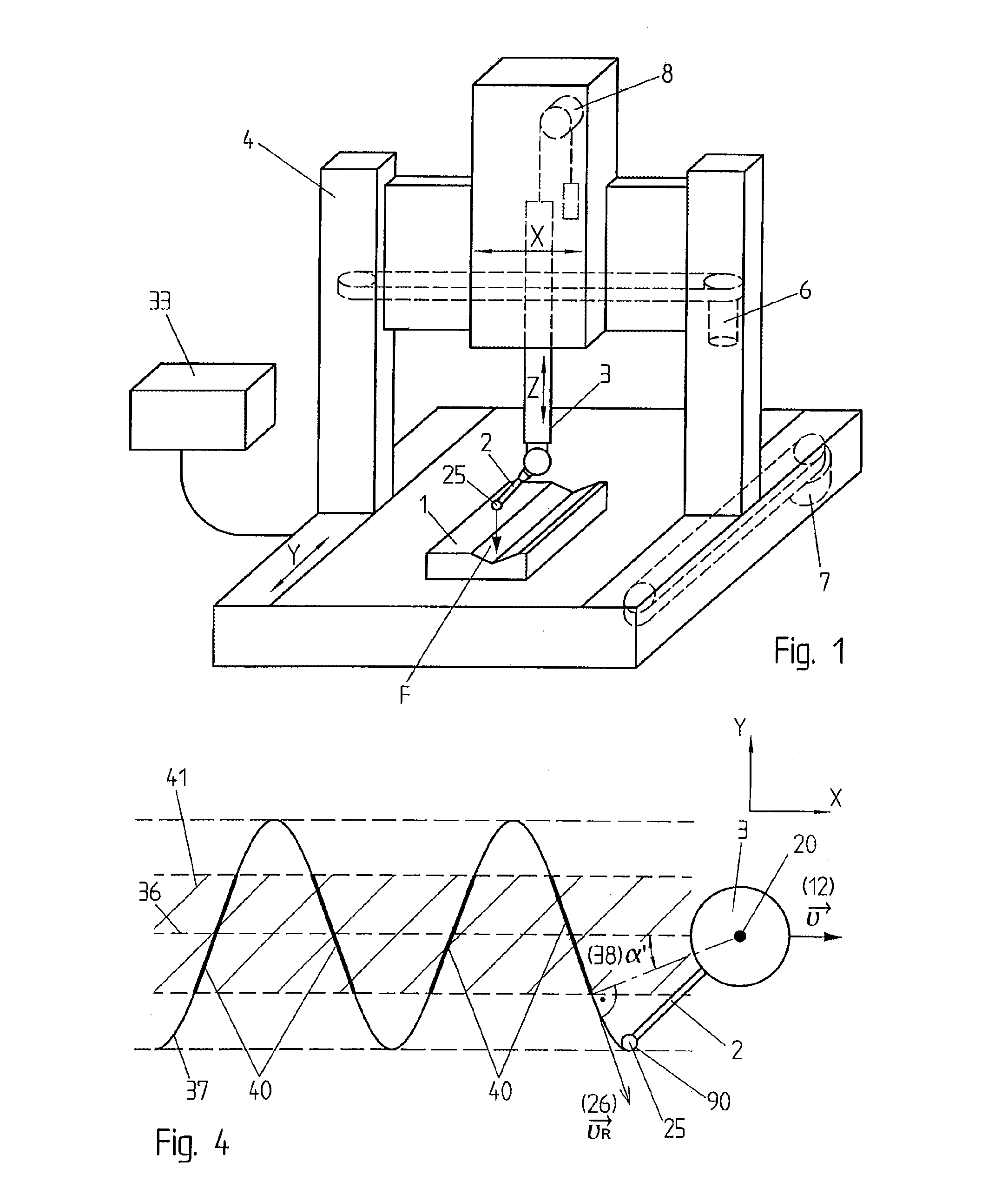
[0023]A coordinate measuring machine 4 is disclosed in FIG. 1 according to a preferred embodiment of the invention. Such a machine 4 is also known as CMM. The CMM 4 comprises a scanning probe 2 attached to a support 3. The support 3 can be moved in any linear direction (X, Y, Z), whereas the scanning probe 2 has two degrees of freedom in rotation with respect to the support 3. In this example, the axes for the rotation of the probe are vertical, respectively horizontal, but other combinations of axes could be considered (e.g. two independent orthogonal horizontal axes, or any number of rotational axes, or any combination of rotational and linear degrees of freedom).

[0024]According to the circumstances, the CMM could be equipped with several kind of measuring probes, including, for example, but not exclusively:

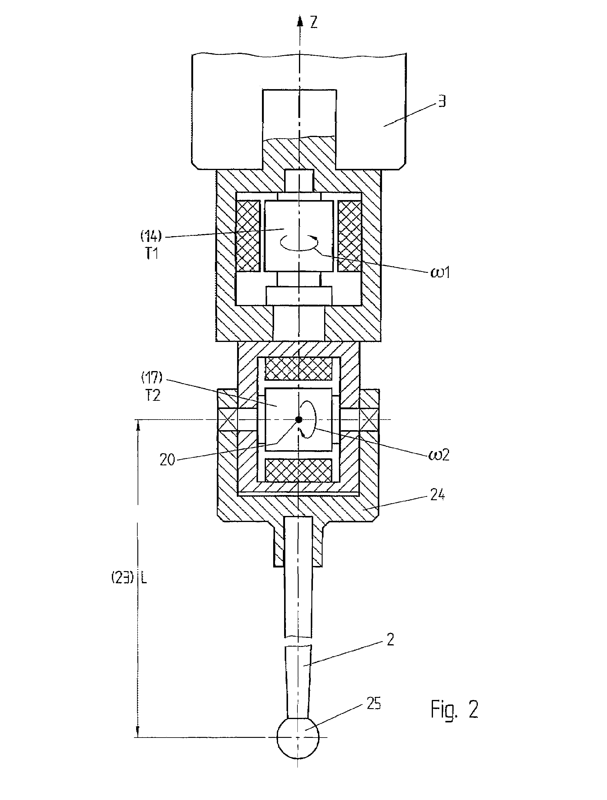
[0025]a contact probe, as represented in FIG. 2, wherein a touch sphere is urged against the surface under measurement, and the coordinates of the contact point are computed by...


PUM


Abstract

A method for scanning a surface of a workpiece 1 at a constant scanning speed / va / using a scanning probe 2 mounted on a support 3 on a coordinate measuring machine (CMM) 4. The CMM contains a first set of drive means (6, 7, 8) to move the support according to three linear axis (x,y,z), and the support 3 contains a second set of drive means (14, 17) for actuating the movement of the scanning probe 2 with two degrees of freedom relative to said support 3. The method involves control means 33 coupled to the sets of drive means (6, 14, 17), and memory means for storing theoretical profiles and coordinates of the surface to scan.

Description

FIELD OF THE INVENTION[0001]The present invention concerns a method for scanning the surface of a workpiece and a related apparatus.DESCRIPTION OF RELATED ART[0002]Numerous methods for scanning are known, in which a mechanical probe is fixed on a machine spindle which traverses the surface of a workpiece in straight lines over each possible direction (x,y,z). After each line is completed the machine spindle moves the probe to a new position displaced from the completed line and repeats the movement along a parallel line.[0003]One major drawback of these methods known from the art is that they are relatively slow for scanning complex forms, since the whole machine needs to be moved backwards and forwards while covering the whole scanning area of the surface. Furthermore, the accelerations and decelerations of the machine can introduce inaccuracies in the measurement process because of the strong inertia forces due to the large mass of the pieces in charge of positioning the surface d...

Claims


Application Information

Patent Timeline
Patent Type & Authority Patents(United States)
IPC IPC(8): G01B5/008
CPCG01B21/045
Inventor JORDIL, PASCALKNUT, SIERCKSPETTERSSON, BOWILCOX, WILLIAM
Owner HEXAGON METROLOGY A B (SE)
Why Eureka
Try Eureka