Image display system with light pen

a technology of image display and light pen, which is applied in the field of image display system having a light pen, can solve the problems of light detect sensor malfunction, touch screen panel weight and volume increase, and touch screen panel is inappropria

Active Publication Date: 2010-01-19
SAMSUNG DISPLAY CO LTD
View PDF13 Cites 117 Cited by
  • Summary
  • Abstract
  • Description
  • Claims
  • Application Information

AI Technical Summary

Problems solved by technology

However, the touch screen panel increases weight and volume of the display device.
Further, when an image or a picture to be displayed on the touch screen is minute, the touch screen panel is inappropriate.
As a result, the light detect sensor may malfunction due to the decrease in the amount of the light provided to the light detect sensor.
Further, the light pen includes the light source, such as a light emitting diode, to generate the light, it is inevitable to cause an increase in its weight and volume and manufacturing cost.

Method used


Image

  • Image display system with light pen
  • Image display system with light pen
  • Image display system with light pen

Examples


Embodiment Construction

[0045]Detailed illustrative embodiments of the present invention are disclosed herein. However, specific structural and functional details disclosed herein are merely representative for purposes of describing exemplary embodiments of the present invention.

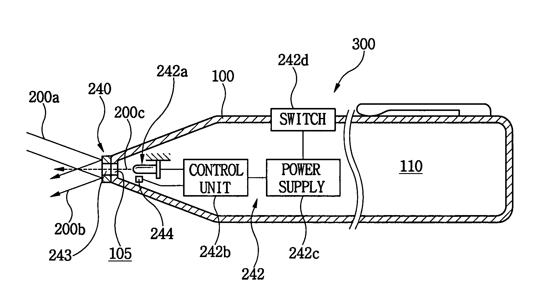
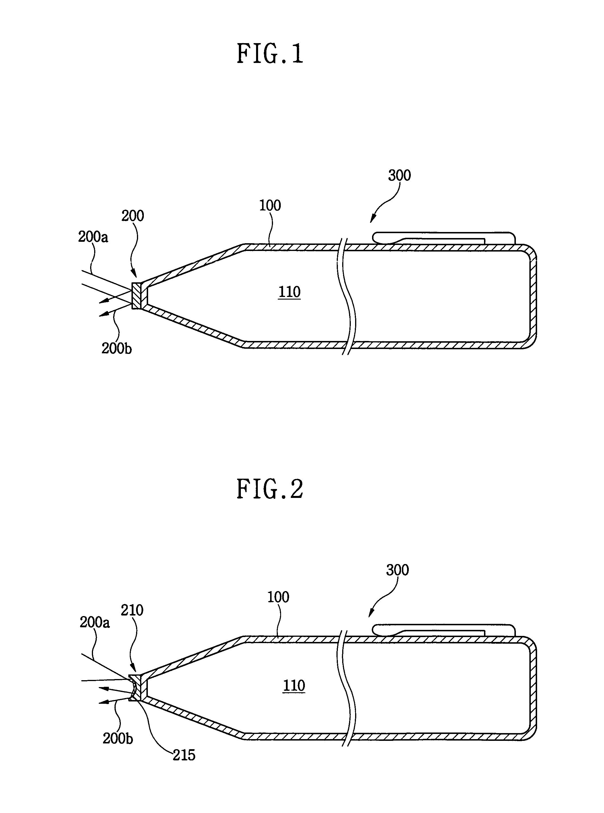
[0046]FIG. 1 is a cross-sectional view of a light pen according to an exemplary embodiment of the present invention. Referring to FIG. 1, the light pen 300 includes a body 100 and a light converting part 200. The light converting part 200 is disposed at the end portion of the body 100, and has, for example, a disc shape. The body 100 is narrowed to form the end portion of the body 100. The light converting part 200 converts image light 200a into a first sensing light 200b. The image light 200a is generated from a display device (not shown) and advances toward the light converting part 200. The image light 200a is then reflected by the light converting part 200, and the reflected light is provided as the first sensing light 200b, wh...


PUM

PropertyMeasurementUnit
diffused reflectionaaaaaaaaaa
electric poweraaaaaaaaaa
optical propertiesaaaaaaaaaa

Abstract

An image display system includes a light pen to generate light to input data, and a display panel to display images in response to the light provided from the light pen. The display panel includes a first substrate on which pixel electrodes are formed, a second substrate on which a common electrode are formed, and a photo-sensor formed on the first substrate. The photo-sensor detects the light provided from the light pen to generate a light detect signal. The image display system also includes a driving module to provide new image data to the display panel to display new images in response to the light detect signal from the photo-sensor.

Description

BACKGROUND OF THE INVENTION[0001]1. Field of the Invention[0002]The present invention relates to a system for displaying images, and more particularly, to an image display system having a light pen to input information.[0003]2. Description of the Related Art[0004]Generally, conventional image display devices have such a data interface function that electrical data provided from an image data processing device is converted into images. In the conventional image display devices, the electrical data from the image data processing device is externally inputted using various input devices, such as a keyboard, a key pad, a mouse, etc.[0005]Recently developed display devices have a screen which is capable of receiving input data, and the input data is processed to display the processed data on the screen. In other words, a display device and an input device are unified in such display devices.[0006]To configure a display system having the unified display device and the input device, the di...

Claims


Application Information

Patent Timeline
Patent Type & Authority Patents(United States)
IPC IPC(8): G09G3/28G06F3/042G02F1/13G02F1/133G02F1/135G02F1/1362G06F3/033G06F3/041G09F9/00
CPCG02F1/1354G02F1/1362G06F3/03542G06F3/0386G06F3/0412G06F3/042G02F1/13338
Inventor CHO, JONG-WHANPARK, SANG-JINPARK, JONG-WOUNGLEE, MYUNG-WOOUH, KEE-HANKIM, HYUNG-GUELCHOI, YOUNG-JUNJUNG, YOUNG-BAE
Owner SAMSUNG DISPLAY CO LTD
Why Eureka
Try Eureka