Video visitation system and method for a health care location

a video visitation system and health care technology, applied in the field of patients' care, can solve the problems of unacceptably high icu mortality rate, clinical complications, serious disability or death, etc., and achieve the effect of minimizing adverse events, economic benefits, and minimizing complications and adverse events

Inactive Publication Date: 2010-01-19
VISICU
View PDF88 Cites 144 Cited by
  • Summary
  • Abstract
  • Description
  • Claims
  • Application Information

AI Technical Summary

Benefits of technology

[0039]The advantage of the present invention is that intensivists see all patients at a plurality of ICU's at all times. Further, there is a continuous proactive intensivist care of all patients within the ICU, thereby minimizing adverse events. Intervention is triggered by evidence-based data-driven feedback to the intensivist so that standardized care can be provided across a plurality of ICUs.
[0040]The economic benefits of the present invention are manifold. For the first time, 24-hour a day, seven day a week intensivist care for patients in an ICU can be obtained. Further, more timely interventions in the care of the patients can be created by the knowledge-based guidelines of the present invention, thereby minimizing complications and adverse events. This in turn will lead to a reduced mortality within the ICU, and hence, a reduced liability cost due to the dramatic reduction in avoidable errors in health care.
[0041]By providing timely interventions, the length of stay within the ICU can be greatly reduced, thereby allowing more critically ill patients to be cared for in the ICU.
[0042]In addition, by reviewing and standardizing the care afforded to patients in an ICU, a more standardized practice across a variety of ICUs can be achieved. This will lead to more cost-effective care within the ICU, and reduced ancillary cost for the care of the critically ill.
[0043]The overall architecture of the present invention comprises a “pod.” The pod comprises a tele-medicine command center / remote location connected to a plurality multiple ICUs at various locations. The connection between the command center / remote location and the ICUs is via a dedicated wide-area network linking the ICUs to the command center / remote location and a team of intensivists who integrate their services to provide 24-hour, seven day a week care to all of the pod ICUs.
[0044]The pod is connected via a wide-area network using dedicated T-1 lines, for example, with redundant backup. This network provides reliable, high speed secure transmission of clinical data and video / audio signals between each patient room and the command center / remote location. The use of a T-1 line is not meant as a limitation. It is expected that more and higher bandwidth networks will become available. Such high bandwidth networks would come within the scope of the invention as well.

Problems solved by technology

The result of this mismatch between severity of illness and physician coverage is an unacceptably high ICU mortality rate (10% nationwide), and a high prevalence of avoidable errors that result in clinical complications.
In another prominent 1998 study of 1000 patients, 46% experienced an avoidable adverse event in care, with 40% of these errors resulting in serious disability or death.
The physicians who can remedy this situation are in critically short supply.
With the rapid aging of the population, this shortfall of expertise is going to increase dramatically.
Even where Intensivists are present (and especially where they are not), patients suffer from unnecessary variation in practice.
There is little incentive for physicians to develop and conform to evidence-based best practices (it takes significant work and a change in behavior to develop and implement them).
While these inventions provide useful records management and diagnostic tools, none of them provides a comprehensive method for monitoring and providing real time critical care at disparate ICUs.
Further, none of these inventions provide for the care of a full time intensivist backed by appropriate database and decision support assistance in the intensive care environment.

Method used


Image

  • Video visitation system and method for a health care location
  • Video visitation system and method for a health care location
  • Video visitation system and method for a health care location

Examples


Embodiment Construction

[0162]The present invention is a system and method for remote monitoring of ICU's from a distant command center / remote location. By monitoring a plurality of ICU's remotely, intensivists can better spread their expertise over more ICU beds that heretofore achievable. The presence of 24-hour a day / 7 day-per-week intensivist care dramatically decreases the mortality rates associated with ICU care.

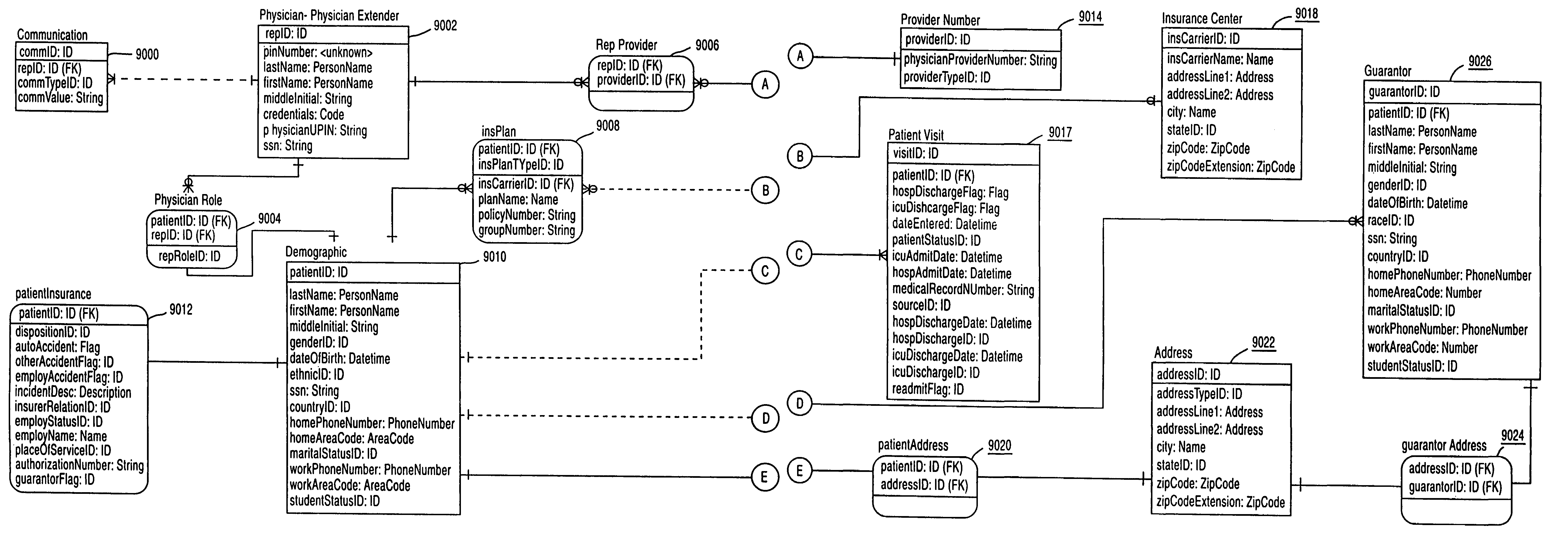
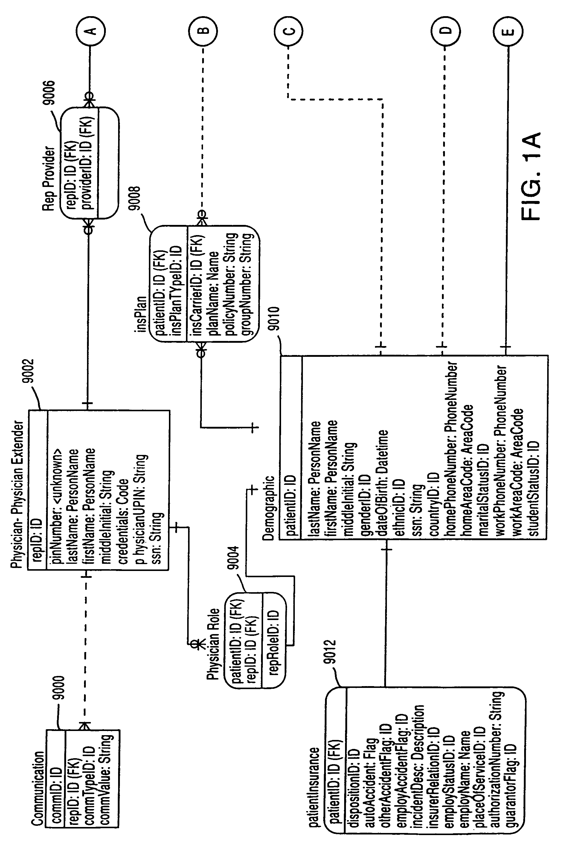
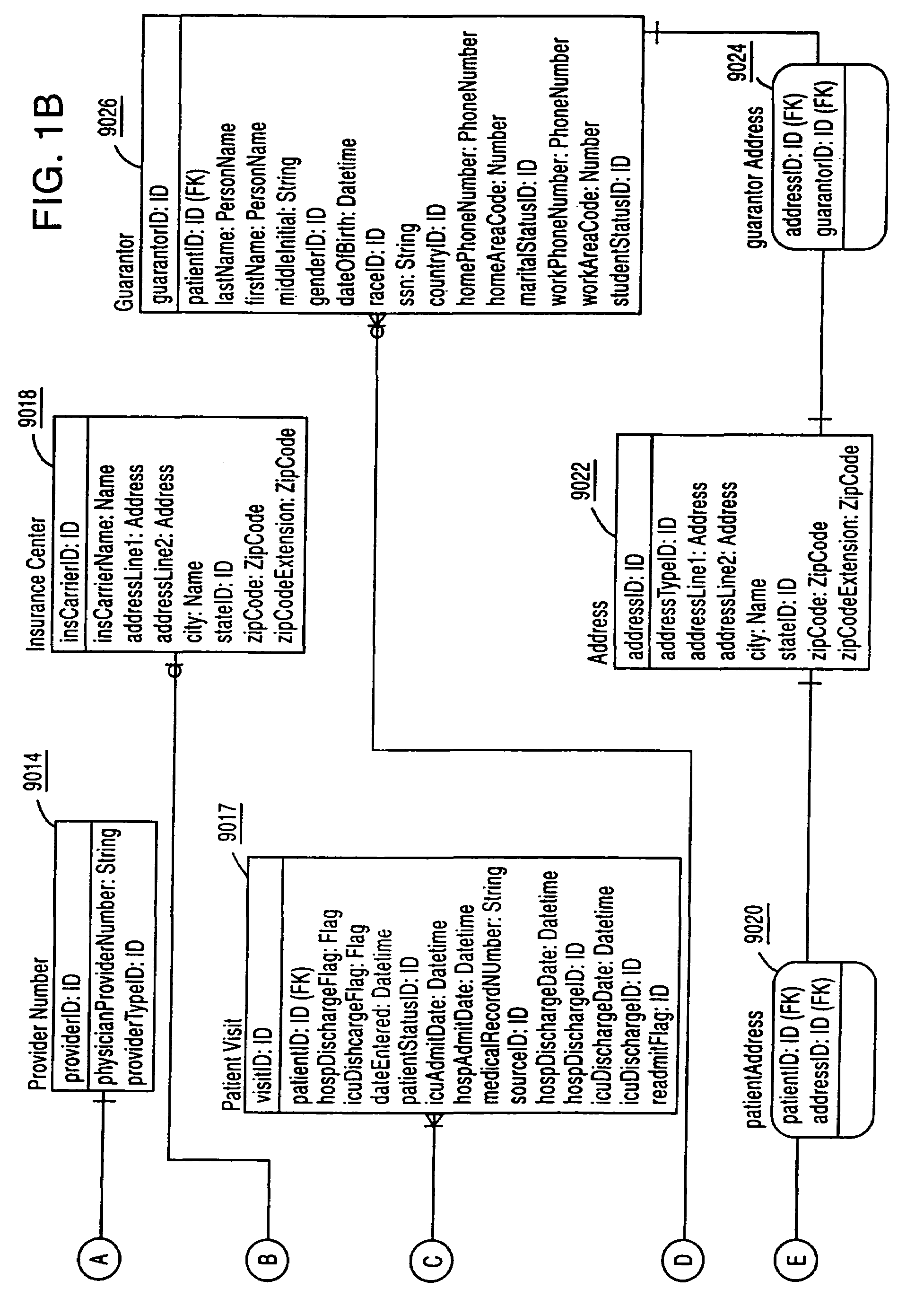
[0163]Referring to FIGS. 1A and 1B, the Billing and Demographic data structure of the present invention is illustrated. Patient demographic information 9010 is collected on the particular patient. This information comprises all the typical kinds of information one would normally gather on a patient such as first name, last name, telephone number, marital status, and other types of information. Patient insurance information 9012 is collected and associated with the patient demographic information 9010. Patient insurance information 9012 relates to information on the type of accident and relate...


PUM


Abstract

A video visitation system and method for dispersed health care locations. A patient data server, a teleconferencing server, a patient visual monitoring system and a visitor visual monitoring system are connected to a network. A patient data server receives patient data indicative of the condition of a patient and serves the patient data continuously and in real time to the teleconferencing server. The patient visual monitoring system acquires patient imaging data from a patient location and conveys the patient imaging data to the teleconferencing server. The visitor visual monitoring system acquires visitor imaging data from a visitor location and conveys the visitor imaging data to the teleconferencing server. The patient visual monitoring system displays the visitor imaging data and the visitor visual monitoring system simultaneously displays patient imaging data and the continuous real time feed of the patient data.

Description

RELATIONSHIP TO OTHER APPLICATIONS[0001]This application is a continuation in part of application Ser. No. 10 / 654,668 filed Sep. 4, 2003 now U.S. Pat. No. 7,475,019 and a continuation in part of application Ser. No. 10 / 946,548 filed Sep. 21, 2004 now U.S. Pat. No. 7,256,708, both of which are continuations in part of application Ser. No. 09 / 443,072 filed Nov. 18, 1999, now U.S. Pat. No. 6,804,656 issued Oct. 12, 2004, which claims the benefit of U.S. Provisional Application No. 60 / 141,520, filed Jun. 23, 1999. The Ser. Nos. 10 / 654,668, 10 / 946,548, 09 / 443,072, and the 60 / 141,520 applications are hereby incorporated by reference in their entirety for all purposes.FIELD OF THE INVENTION[0002]This invention relates generally to the care of patients in Intensive Care Units (ICUs). More particularly this invention is a system and method for care of the critically ill that combines a real-time, multi-node telemedicine network and an integrated, patient care management system to enable spec...

Claims


Application Information

Patent Timeline
Patent Type & Authority Patents(United States)
IPC IPC(8): G06Q10/00A61B5/00A61B5/0205G08B21/04G16H10/60G16H20/40G16H40/67G16H50/20G16H70/20G16H80/00
CPCA61B5/7465G06F19/322G06F19/325G06F19/327G06F19/3418G06F19/3425G06F19/345G06F19/3481G06Q50/22G06Q50/24G08B21/0476A61B5/4094A61B5/412A61B5/0205G06F19/328A61B5/002A61B5/0022G16H80/00G16H10/60G16H40/20G16H50/20G16H70/20G16H40/67G06Q40/08G16H20/40
Inventor ROSENFELD, BRIAN A.BRESLOW, MICHAEL
Owner VISICU
Why Eureka
Try Eureka