Unlock instant, AI-driven research and patent intelligence for your innovation.

Ferroelectric memory having a refresh control circuit capable of recovering residual polarization of unselected memory cells

a control circuit and memory technology, applied in the field of memory, can solve problems such as data loss from unselected memory cells, and achieve the effects of reducing the frequency of disturbance, reducing the frequency of reading and rewriting, and facilitating reading and rewriting

Active Publication Date: 2010-01-26
OL SECURITY LIABILITY CO
View PDF19 Cites 7 Cited by
  • Summary
  • Abstract
  • Description
  • Claims
  • Application Information

AI Technical Summary

Benefits of technology

The present invention provides a memory that can prevent data loss from unselected memory cells caused by a disturbance phenomenon. The memory includes a memory cell array with a bit line and a word line, and a first and second voltage pulse that provide an electrical field in opposite directions to cancel out residual polarization. The memory also performs a recovery operation on the unselected memory cells by applying the first and second voltage pulses to read, write, or erase the memory cells. The recovery operation can be performed on a selected memory cell while inhibiting deterioration of the residual polarization in the unselected memory cells. The memory cell can also be recovered from deterioration of the residual polarization by performing the recovery operation on a selected word line. The memory cell array can include a selected memory cell and an unselected memory cell, and the recovery operation can be performed on all memory cells linked to the selected word line or collectively performed on all memory cells linked to the selected word line.

Problems solved by technology

Consequently, there is such a problem that such a disturbance phenomenon takes place that data are lost from the unselected memory cells 501.

Method used


Image

  • Ferroelectric memory having a refresh control circuit capable of recovering residual polarization of unselected memory cells
  • Ferroelectric memory having a refresh control circuit capable of recovering residual polarization of unselected memory cells
  • Ferroelectric memory having a refresh control circuit capable of recovering residual polarization of unselected memory cells

Examples


first embodiment

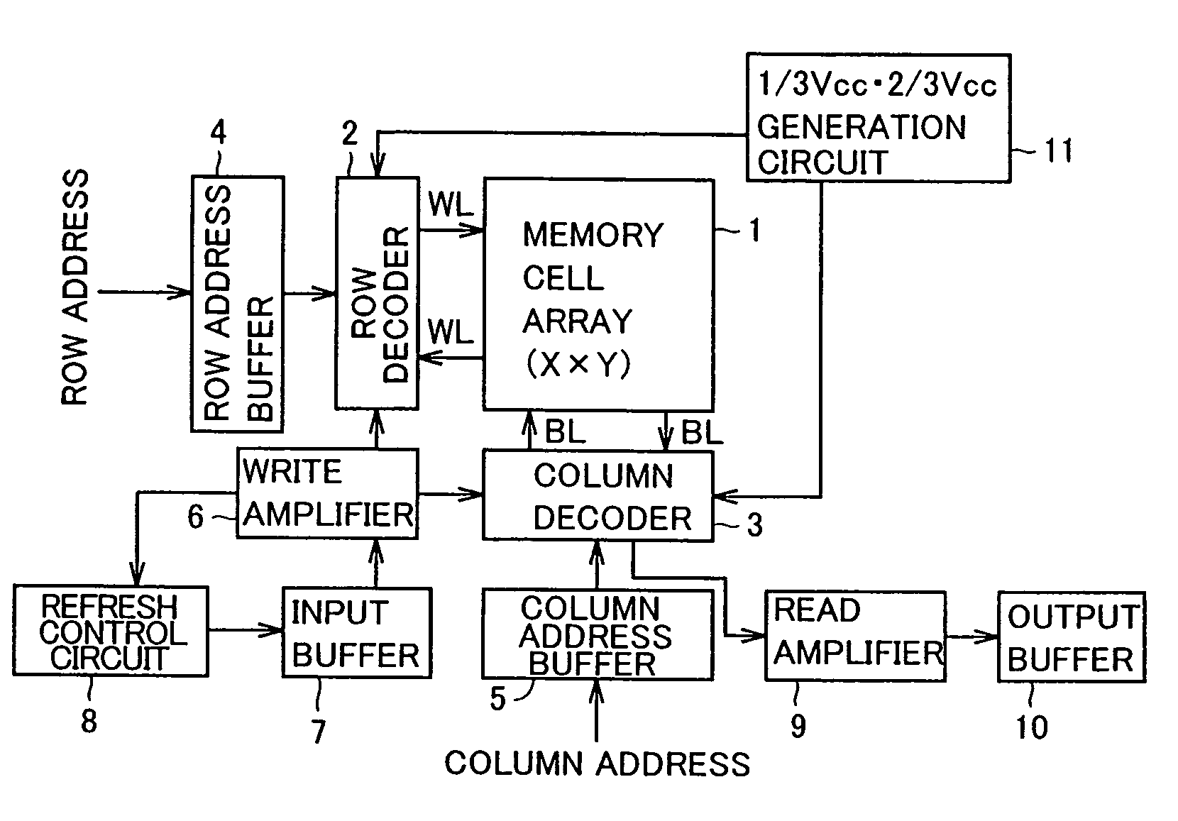
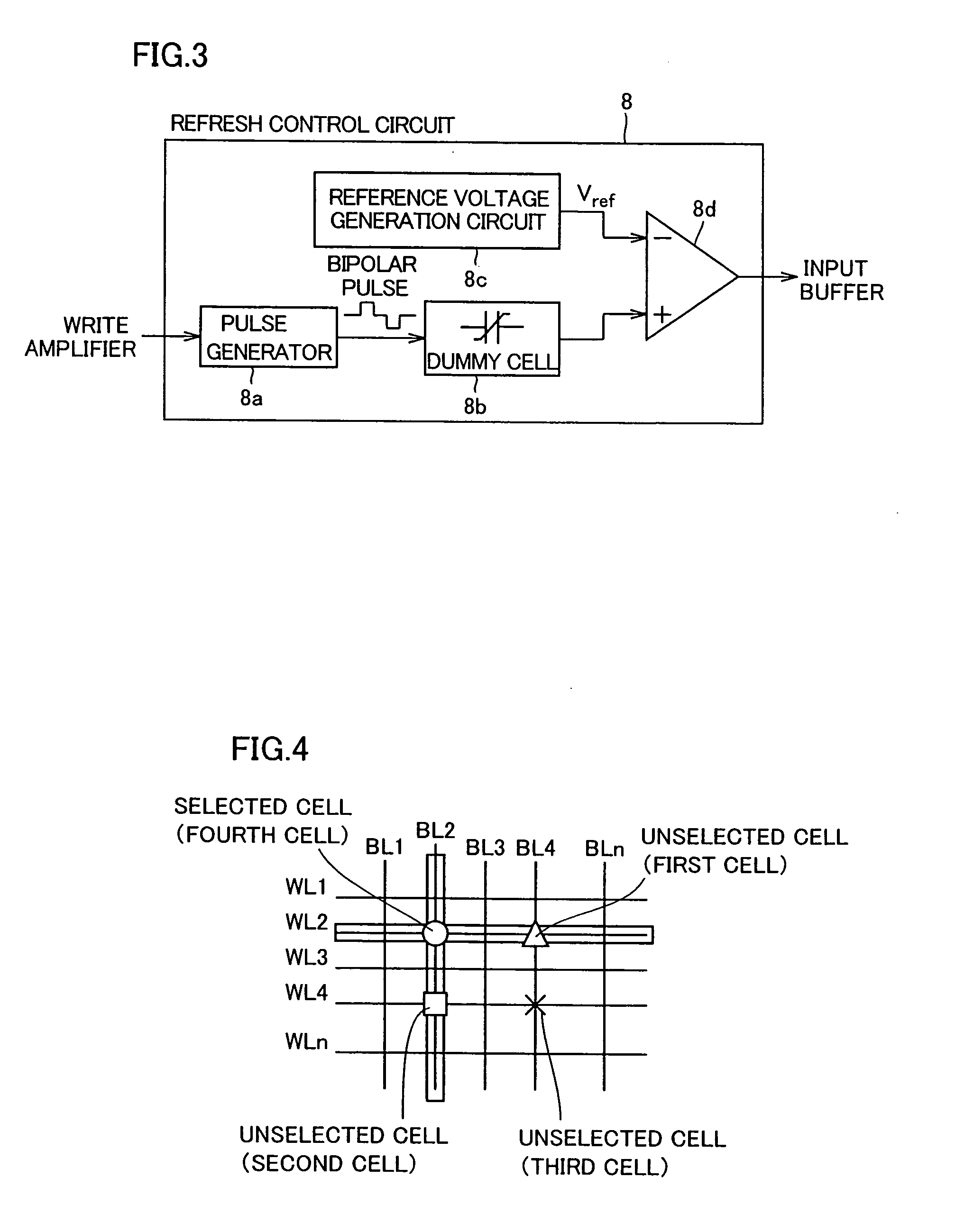
[0084]First, the structure of a simple matrix ferroelectric memory according to a first embodiment is described with reference to FIGS. 1 to 3. The ferroelectric memory according to the first embodiment comprises a memory cell array 1, a row decoder 2, a column decoder 3, a row address buffer 4, a column address buffer 5, a write amplifier 6, an input buffer 7, a refresh control circuit 8, a read amplifier 9 formed by a voltage sense amplifier, an output buffer 10 and a ⅓ Vcc·⅔ Vcc generation circuit 11. The refresh control circuit 8 is an example of the “recovery operation control circuit” in the present invention.

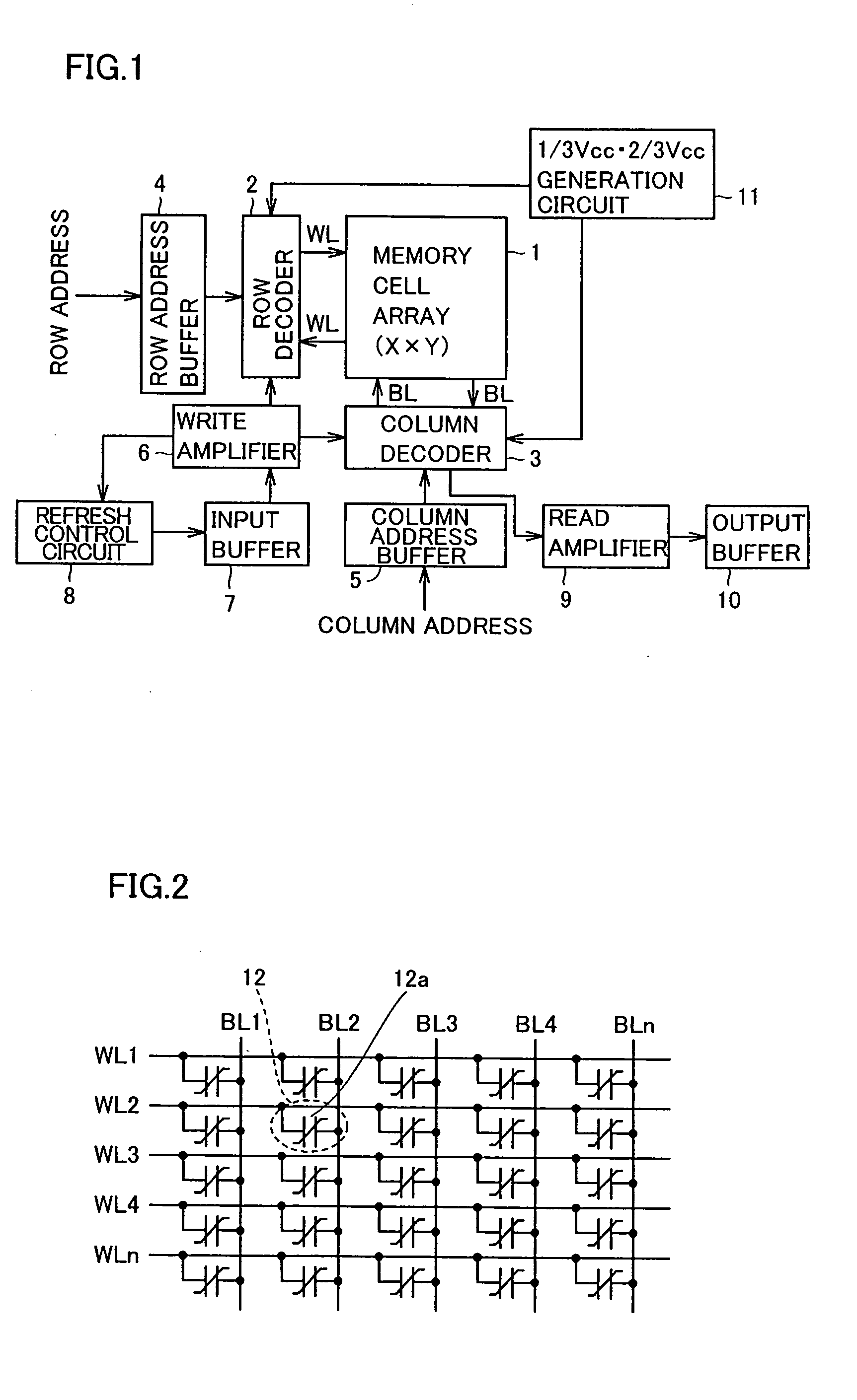
[0085]The memory cell array 1 includes a plurality of simple matrix memory cells 12 formed by only ferroelectric capacitors 12a, as shown in FIG. 2. In other words, the simple matrix memory cells 12 according to the first embodiment are constituted of the ferroelectric capacitors 12a consisting of word lines WL and bit lines BL formed to extend in directions intersecting ...

second embodiment

[0128]This second embodiment is described with reference to an example of applying the present invention to a case of collectively accessing all memory cells connected to an arbitrary word line WL of a ferroelectric memory, dissimilarly to the aforementioned first embodiment.

[0129]Referring to FIG. 12, a read amplifier 19 is directly connected to a memory cell array 1 in the ferroelectric memory according to the second embodiment. The remaining structure of the ferroelectric memory according to the second embodiment is similar to the structure of the ferroelectric memory according to the aforementioned first embodiment.

[0130]Operations of the ferroelectric memory according to the second embodiment are now described with reference to FIGS. 12 to 16. In the description of the second embodiment, it is assumed that a selected WL is a word line WL5, as shown in FIG. 13. It is also assumed that data “1” are stored in memory cells connected to a bit lines BL4 and BL6 among memory cells con...

third embodiment

[0156]The structure of a ferroelectric memory according to a third embodiment of the present invention is now described with reference to FIGS. 17 and 18.

[0157]The ferroelectric memory according to the third embodiment comprises a memory cell array 21, a row decoder 22, a refresh control circuit 23, a clock generation circuit 27 including a counter 24, an access detecting portion 25 and a state machine circuit 26, a row address buffer 28, a column address buffer 29, a write amplifier 30, a read amplifier 31, an input buffer 32, an output buffer 33, a column decoder 34, a word line source driver 35, a voltage generation circuit 36, a sense amplifier 37 an a bit line source driver 38, as shown in FIG. 17. The refresh control circuit 23 is an example of the “refresh portion” in the present invention, and the counter 24 is an example of the “first frequency detecting portion” in the present invention.

[0158]In the memory cell array 21, a plurality of word lines WL and a plurality of bit ...


PUM


Abstract

A memory wherein any “disturb effect” can be suppressed in which data in unselected memory cells are lost. This memory has a memory cell array (1) including bit lines, word lines, which are disposed to intersect the bit lines, and memory cells (12) each connected between bit and word lines. In this memory, an access operation, which includes at least one of read, rewrite and write operations, is made to a selected memory cell (12). During this access operation, it is performed to apply to the memory cell (12) a first voltage pulse, which provides an electrical field in a first direction so as to invert a stored data, and a second voltage pulse, which provides as electrical field in the opposite direction to the first one so as not to invert the stored data. In addition, a recovery operation for recovering a residual polarization amount is made to the memory cell (12).

Description

TECHNICAL FIELD[0001]The present invention relates to a memory.BACKGROUND ART[0002]In general, a ferroelectric memory is known as one of nonvolatile memories. Such a ferroelectric memory is disclosed in Japanese Patent Laying-Open No. 2001-210795, for example. This conventional ferroelectric memory is a memory utilizing a pseudo-capacitance change responsive to the direction of polarization of a ferroelectric substance as a memory device. The ferroelectric memory is spotlighted as an ideal memory having both of such an advantage that the same can rewrite data at a high speed with a low voltage in principle and such an advantage that the same is nonvolatile.[0003]FIG. 33 is an equivalent circuit diagram showing a memory cell array of an exemplary conventional simple matrix ferroelectric memory. FIG. 34 is a hysteresis diagram for illustrating operations of the exemplary conventional simple matrix ferroelectric memory. Referring to FIG. 33, a memory cell 501 of the exemplary conventio...

Claims


Application Information

Patent Timeline
Patent Type & Authority Patents(United States)
IPC IPC(8): G11C11/22
CPCG11C11/22G11C11/221G11C11/2273G11C11/2275G11C11/2297
Inventor MIYAMOTO, HIDEAKISAKAI, NAOFUMIYAMADA, KOUICHIMATSUSHITA, SHIGEHARU
Owner OL SECURITY LIABILITY CO