Memory
a technology of memory and memory cells, applied in the field of memory, can solve the problems of data loss from unselected memory cells, and achieve the effects of reducing the frequency of disturbance, reducing the frequency of reading, and facilitating reading and rewriting
- Summary
- Abstract
- Description
- Claims
- Application Information
AI Technical Summary
Benefits of technology
Problems solved by technology
Method used
Image
Examples
first embodiment
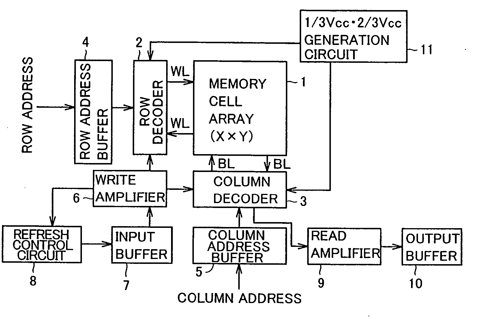
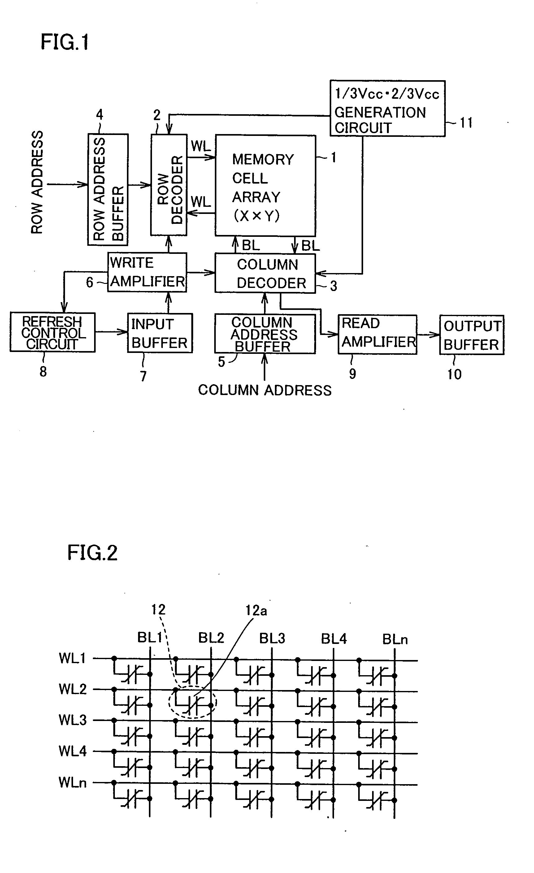
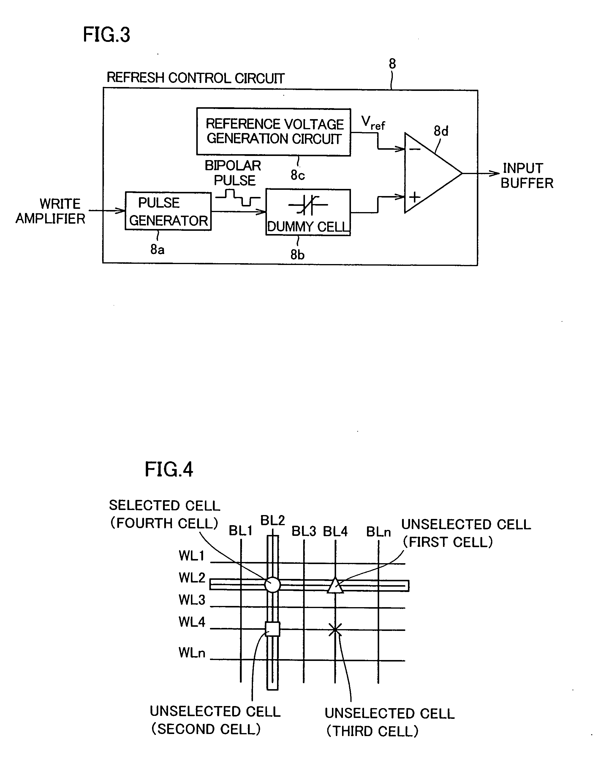
[0083] First, the structure of a simple matrix ferroelectric memory according to a first embodiment is described with reference to FIGS. 1 to 3. The ferroelectric memory according to the first embodiment comprises a memory cell array 1, a row decoder 2, a column decoder 3, a row address buffer 4, a column address buffer 5, a write amplifier 6, an input buffer 7, a refresh control circuit 8, a read amplifier 9 formed by a voltage sense amplifier, an output buffer 10 and a ⅓Vcc-⅔Vcc generation circuit 11. The refresh control circuit 8 is an example of the “recovery operation control circuit” in the present invention.
[0084] The memory cell array 1 includes a plurality of simple matrix memory cells 12 formed by only ferroelectric capacitors 12a, as shown in FIG. 2. In other words, the simple matrix memory cells 12 according to the first embodiment are constituted of the ferroelectric capacitors 12a consisting of word lines WL and bit lines BL formed to extend in directions intersecting...
second embodiment
[0127] This second embodiment is described with reference to an example of applying the present invention to a case of collectively accessing all memory cells connected to an arbitrary word line WL of a ferroelectric memory, dissimilarly to the aforementioned first embodiment.
[0128] Referring to FIG. 12, a read amplifier 19 is directly connected to a memory cell array 1 in the ferroelectric memory according to the second embodiment. The remaining structure of the ferroelectric memory according to the second embodiment is similar to the structure of the ferroelectric memory according to the aforementioned first embodiment.
[0129] Operations of the ferroelectric memory according to the second embodiment are now described with reference to FIGS. 12 to 16. In the description of the second embodiment, it is assumed that a selected WL is a word line WL5, as shown in FIG. 13. It is also assumed that data “1” are stored in memory cells connected to a bit lines BL4 and BL6 among memory cell...
third embodiment
[0155] The structure of a ferroelectric memory according to a third embodiment of the present invention is now described with reference to FIGS. 17 and 18.
[0156] The ferroelectric memory according to the third embodiment comprises a memory cell array 21, a row decoder 22, a refresh control circuit 23, a clock generation circuit 27 including a counter 24, an access detecting portion 25 and a state machine circuit 26, a row address buffer 28, a column address buffer 29, a write amplifier 30, a read amplifier 31, an input buffer 32, an output buffer 33, a column decoder 34, a word line source driver 35, a voltage generation circuit 36, a sense amplifier 37 an a bit line source driver 38, as shown in FIG. 17. The refresh control circuit 23 is an example of the “refresh means” in the present invention, and the counter 24 is an example of the “first frequency detecting means” in the present invention.
[0157] In the memory cell array 21, a plurality of word lines WL and a plurality of bit...
PUM
 Abstract
Description
Claims
Application Information
 - R&D
- Intellectual Property
- Life Sciences
- Materials
- Tech Scout
- Unparalleled Data Quality
- Higher Quality Content
- 60% Fewer Hallucinations
Browse by: Latest US Patents, China's latest patents, Technical Efficacy Thesaurus, Application Domain, Technology Topic, Popular Technical Reports.
© 2025 PatSnap. All rights reserved.Legal|Privacy policy|Modern Slavery Act Transparency Statement|Sitemap|About US| Contact US: help@patsnap.com


