Establishing relationships between objects based on object interfaces

a technology of object interface and relationship, applied in the field of object-oriented databases, can solve the problems of reducing the functionality of objects of different types, unable to achieve granularity, and unable to reduce the overhead of objects, so as to achieve efficient and convenient linkage

Inactive Publication Date: 2010-02-02
MICROSOFT TECH LICENSING LLC
View PDF12 Cites 2 Cited by
  • Summary
  • Abstract
  • Description
  • Claims
  • Application Information

AI Technical Summary

Benefits of technology

[0017]It is an object of the present invention to relate objects based on characteristics of the related objects rather than simply the class of the object, thereby allowing objects of different types to be easily related.
[0022]By defining the relationship on an interface of an object rather than the class of the object, objects of different types created by different classes may be easily related based on the same kind of relationship, due to the different classes supporting the same interface. This creates a more intuitive model since it is object characteristics (as defined by interfaces) that provide functional capabilities to clients rather than mechanisms such as class definitions used to create or instantiate an object.
[0026]In a fourth embodiment, the facilities of both the second and third embodiments are combined so that a user has both options available. The more direct collection of objects supporting the related interface provides a more efficient and convenient link when only the related object is desired, while the collection of relationship objects allows behavior to be associated with the relationship itself. Again, both collections on the origin and destination objects are implemented by objects (e.g., one object for each collection) themselves.

Problems solved by technology

While this allows relationships to exist between objects, it lacks granularity for allowing objects of different types to be conventionally related without minimizing object functionality or increasing object overhead.

Method used


Image

  • Establishing relationships between objects based on object interfaces
  • Establishing relationships between objects based on object interfaces
  • Establishing relationships between objects based on object interfaces

Examples


Embodiment Construction

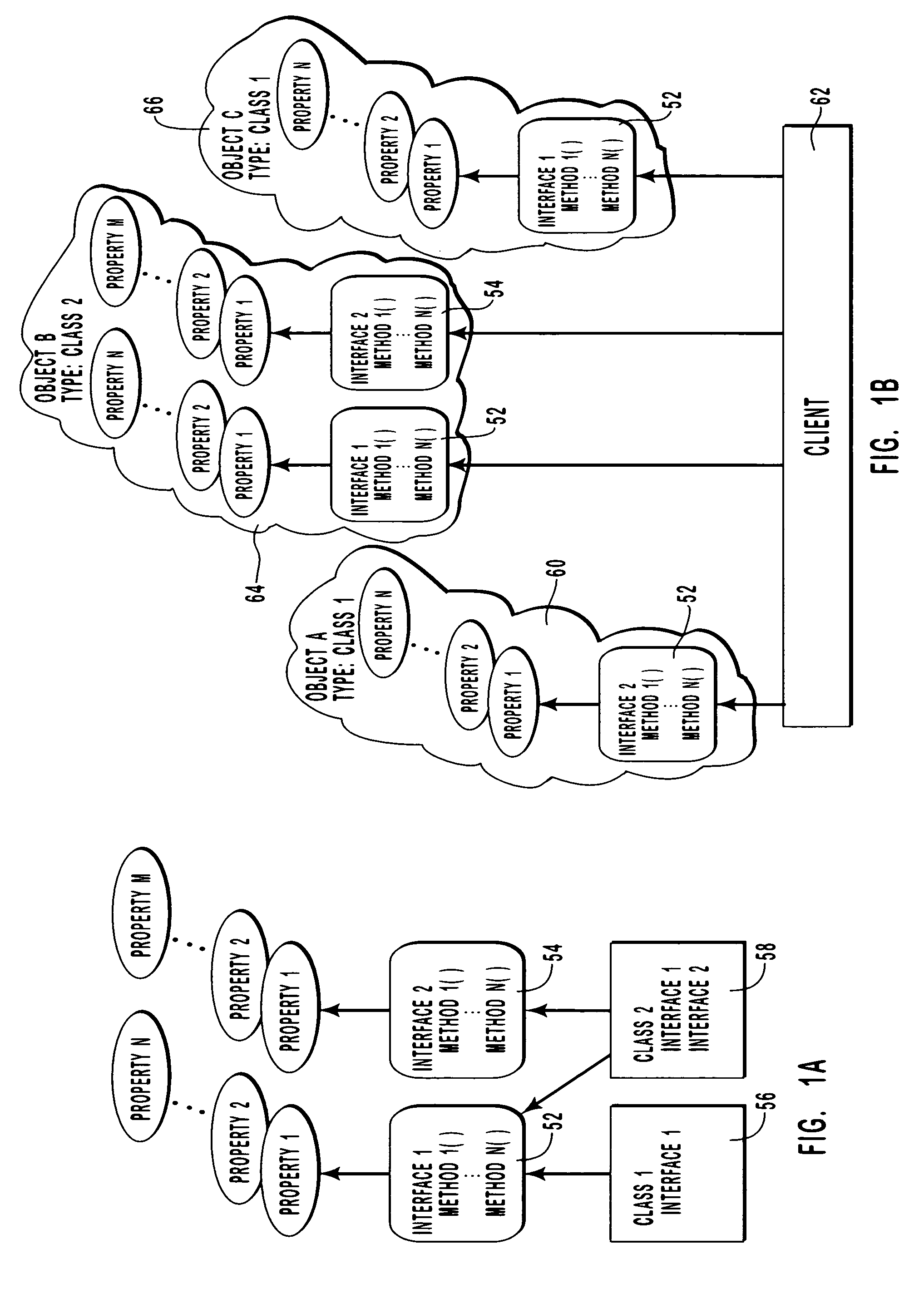
[0042]Throughout this application, reference will be made to objects that are created or instantiated by computer software. Such objects will have a data portion associated therewith for storing information, and have methods or functionality associated therewith to provide desired functionality to a client accessing the object. Typically, the methods of the object will be directed in part to manipulating the object's data. Such an abstract object has an associated state that is the cumulative effect of methods operating on the data. It is this state that will be stored by the innovative object state repository as explained in this application.

[0043]As used herein, the term “objects,” refers to software objects pertaining to a binary object model and that have binary extensibility through wrapping. Furthermore, such objects are interface-based meaning that an object is only used or operated through specific “interfaces” as defined hereafter and an interface-based binary object model ...


PUM


Abstract

In an interface-based object system capable of supporting multiple interfaces into objects, a relationship is defined as a pair of complementary collections on two separate interfaces, each interface found on separate objects. A link between objects is formed when an interface of one object lists an object supporting the related interface included in the object and vice versa. The collections may be of objects supporting the related interfaces or may be of specific relationship objects leading to objects supporting the related interfaces. The collections are potentially multi-valued entities that enable relationships to be established between objects using one-to-one, many-to-one, and many-to-many architectures. By implementing a specific relationship object, behavior may be imparted to the relationship itself thereby providing more robust system behavior. Objects thus linked can be easily traversed so that convenient navigation models can be implemented allowing clients quick access to desired objects by navigating through relationships between objects.

Description

CROSS-REFERENCE TO RELATED APPLICATIONS[0001]The present application is a continuation application of commonly-assigned U.S. patent application Ser. No. 09 / 497,594 filed Feb. 3, 2000 and entitled “Establishing Relationships Between Objects Based on Object Interfaces,” and now issued as U.S. Pat. No. 6,766,518, issued Jul. 20, 2004 which claims priority to U.S. Pat. No. 6,035,342 entitled “Method and Computer Program Product for Implementing Object Relationships”issued Mar. 19, 1997, both of which are incorporated herein by reference.BACKGROUND OF THE INVENTION[0002]1. The Field of the Invention[0003]This invention relates to the field of object-oriented databases wherein navigation between objects is a fundamental method for finding desired data. More specifically, this invention relates to the methods and structures for creating relationships between software objects in order to assist in object navigation.[0004]2. Background and Relevant Art[0005]Object-oriented systems, including...

Claims


Application Information

Patent Timeline
Patent Type & Authority Patents(United States)
IPC IPC(8): G06F7/00G06F9/44
CPCG06F8/24
Inventor BERNSTEIN, PHILIP ALANSHUTT, DAVID R.
Owner MICROSOFT TECH LICENSING LLC
Why Eureka
Try Eureka