
Nail extractor

a technology of extractor and nail, which is applied in the direction of lifting devices, crowbars, metal-working apparatuses, etc., can solve the problems of over-engineering, unwieldy and expensive acquisition, and achieve the effect of quick and effective extraction of partially exposed nail heads

Active Publication Date: 2010-02-09
LAUN CRAIG M
View PDF7 Cites 30 Cited by
  • Summary
  • Abstract
  • Description
  • Claims
  • Application Information

AI Technical Summary

Benefits of technology

"The invention is a device that can quickly and effectively extract partially exposed headed-nails from a substrate. It consists of a housing with elongated sides, a top having a threaded opening, an open bottom, and a port. The device also has a spindle, predominately threaded, with a distal end and a hexagonally-shaped proximal end. The spindle is threaded to rotate in the threaded opening in the top of the housing and to move up and down within the housing in accordance with the counter-clockwise or clockwise rotation of the spindle. At the distal end of the threaded spindle is a claw assembly securely but rotatably attached to the spindle. The claw assembly has a claw formed by a cleft in the assembly, which is capable of engaging with a partially exposed headed nail. The unexposed portion of the nail is typically embedded in a substrate. When properly deployed, the hexagonally-shaped end of the threaded spindle is inserted and securely held by the chuck of a power tool, and the partially exposed nail is fitted within the claw assembly and engaged with the cleft of the claw assembly. The power tool is activated, and the threaded spindle and claw assembly are vertically elevated within the housing, and the grasped nail is extracted from the substrate."

Problems solved by technology

Most of the devices of the prior art are over-engineered, unwieldy and expensive to acquire.

Method used


Image

  • Nail extractor
  • Nail extractor
  • Nail extractor

Examples


Embodiment Construction

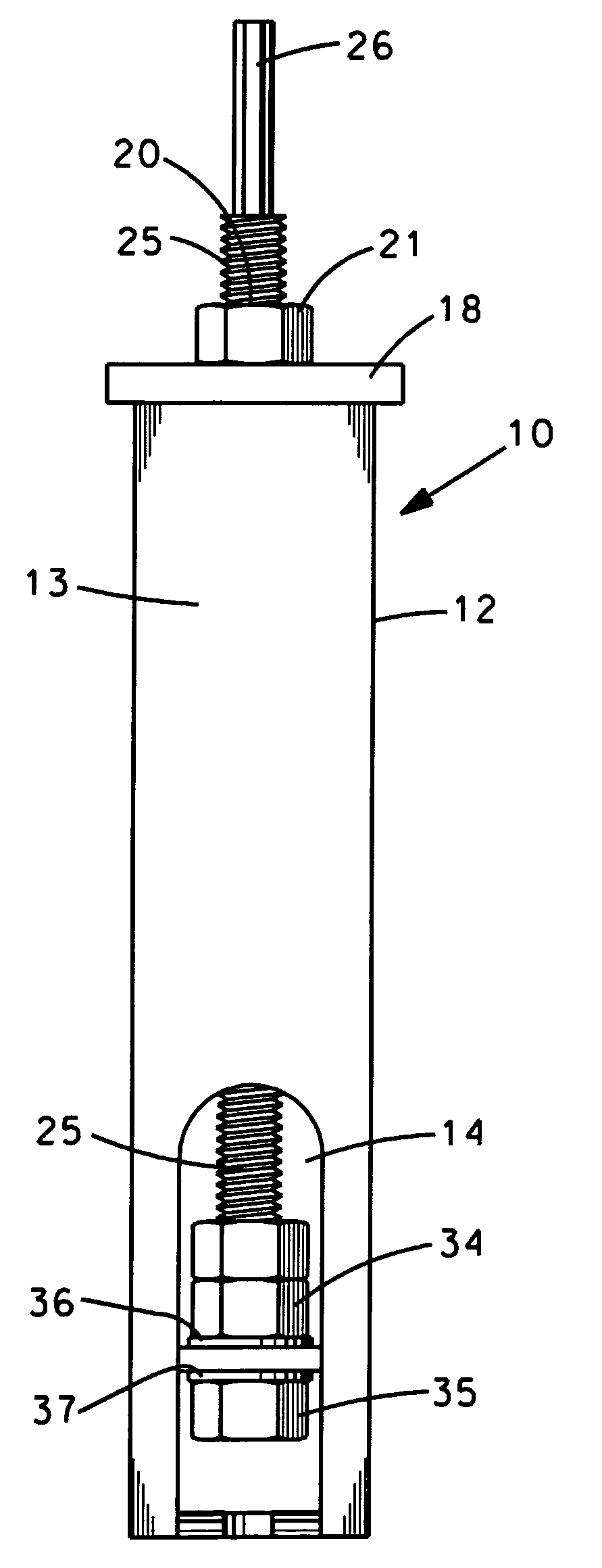
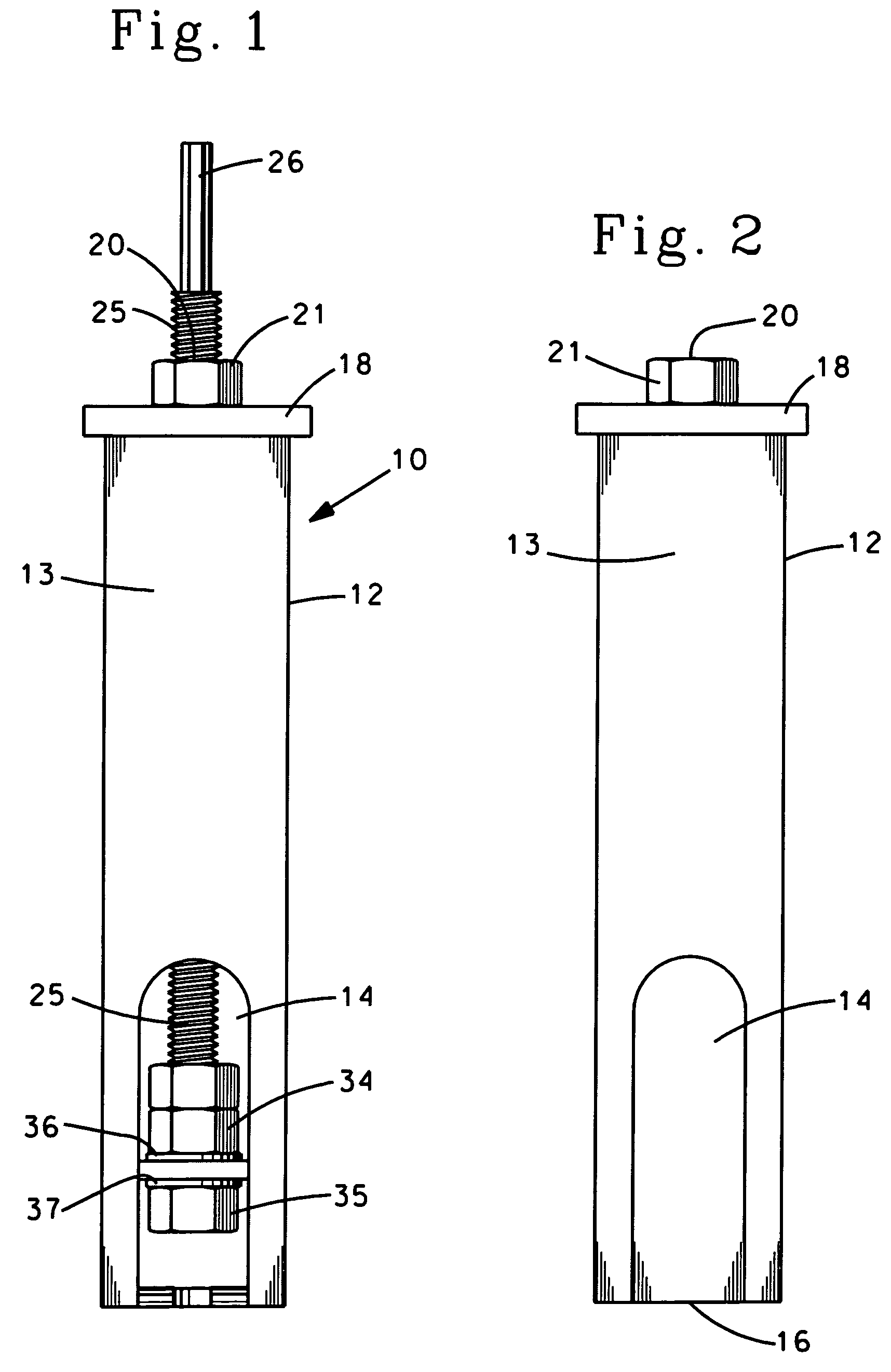
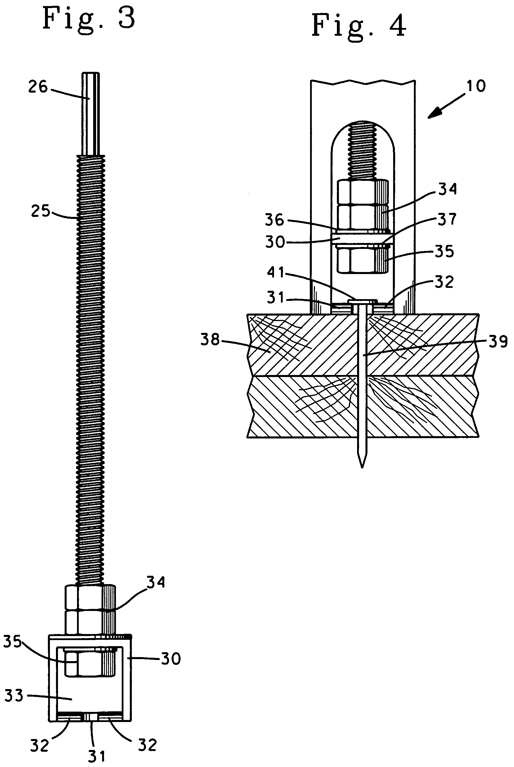
[0013]A full understanding and appreciation of the disclosed invention and its method of use are facilitated by reference to the drawing. Specifically, FIGS. 1, 2 and 3 illustrate the disclosed extractor 10 and all of its elements. While FIG. 1 depicts the extractor 10 assembled for use, initially referring to FIGS. 2 and 3 will aid in an elaboration of the device.

[0014]The device 10 comprises an elongated housing 12 having side walls 13 for support of the threaded spindle 25. The housing 12 also has a top side 18 with a threaded opening 20. The threaded opening, of course is threaded to be compatible with the threads on the threaded spindle 25. To enhance the structure and strength of the threaded opening 20, a threaded dome or nut can be attached to the top 18 of the housing 12 to extend the threaded sides of the opening 20 and strengthen the mechanical relationship between the spindle and the housing.

[0015]The housing 12 (FIG. 2) also requires an open bottom 16, which is contiguo...


PUM

PropertyMeasurementUnit
diameteraaaaaaaaaa
depthaaaaaaaaaa
strengthaaaaaaaaaa

Abstract

Disclosed and described herein is a nail extractor adapted for the powered extraction of partially exposed headed-nails from a substrate. The extractor has a housing with a threaded opening for the fitment of a threaded spindle having a hexagonally-shaped proximal end for the attachment of a power tool and a claw assembly attached to the distal end of the spindle so as to permit free rotation of the spindle while the claw assembly is confined and sized to prevent turning within the housing. Additionally, the claw assembly has a cleft for engaging and grasping the partially exposed portion of the headed nail. When activated by the powered tool, the threaded spindle and claw assembly are vertically elevated within the housing and the partially exposed nail is extracted from the substrate.

Description

CROSS-REFERENCE TO RELATED APPLICATION[0001]This application claims the benefit of the filing date of U.S. Provisional Application 60 / 994,835 filed Sep. 21, 2007.BACKGROUND OF THE INVENTION[0002]The invention disclosed and claimed herein relates generally to a nail extraction device and its method of use. More specifically, it relates to a device for the extraction of headed nails that are partially exposed, meaning that the nails have the head and at least a portion of the nail shank exposed for gripping by the claw of the device. Even more specifically, the invention disclosed herein relates to a device having a claw assembly attached to a threaded spindle that can be turned or rotated by a power tool to remove a partially exposed nail from a substrate. The extraction device described herein, when appropriately powered, replaces crowbars, prybars and claw hammers and minimizes the effort and tedium involved in removing large numbers of nails from reusable substrates, typically lum...

Claims


Application Information

Patent Timeline
Patent Type & Authority Patents(United States)
IPC IPC(8): B25C11/00
CPCB25C11/02Y10T29/53909Y10T29/53843Y10T29/53878
Inventor LAUN, CRAIG M.
Owner LAUN CRAIG M
Learn More