Rope winch

a technology of rope winch and torque sensor, which is applied in the field of rope winch, can solve the problems of high expenditure for repair or exchange of torque sensor, and achieve the effect of simple exchange and simple repair

Active Publication Date: 2010-02-09
ROTZLER HLDG GMBH CO KG
View PDF15 Cites 18 Cited by
  • Summary
  • Abstract
  • Description
  • Claims
  • Application Information

AI Technical Summary

Benefits of technology

[0003]It is an object of the present invention to provide a rope winch of the aforementioned kind that enables a simple exchange and simple repair.
[0004]In accordance with the present invention, this is achieved in that the sensor for detecting the load is arranged on a component that is exchangeably secured on the rope winch without requiring dismounting of a bearing support.
[0006]Advantageously, the component penetrates or extends through the bearing support. In this way, a simple exchangeability is provided. It is also provided that the sensor has a connecting line for connecting it to a control. The connecting line is guided out of the winch through a passage formed within the component. The connecting line is thus integrated into the component so that the exchange of the component together with the sensor can be carried out very simply and very quickly.
[0009]Advantageously, the rope drum is supported with both ends in bearing supports. In this way, high stability and minimal bending forces result. In particular, on one of the bearing supports the drive motor is secured and on the opposite bearing support the gear is supported. It is provided that the gear is supported on the bearing support by means of the component on which the sensor for load detection is arranged. By means of the gear the forces acting on the rope drum are transmitted into the component so that the deformation of the component is a measure of the forces acting on the rope drum.
[0010]Advantageously, the component is a bolt. The gear is in particular a planetary gear whose planet wheels are supported on a stationary planet support. Advantageously, the planet support is fixedly connected to the bolt (no relative rotation is possible). The fixed connection is in particular designed such that it enables a movement of the bolt relative to the planet support in the direction of the drive axis of the rope drum. Accordingly, the bolt can be pulled out of the planet support in the direction of the drive axis. The planet support is secured in the rope drum by means of the planet wheels so that removal of the bolt is possible without problems. Advantageously, the planet support and the bolt are fixedly connected by means of a toothing, in particular, a serration, so that they cannot rotate relative to one another. A toothing enables the transmission of high torque and, at the same, insertion of the component into the planet support in the direction of the drive axis.
[0011]It is provided that the bolt is fixedly connected to the bearing support so that it cannot rotate relative to the bolt. The fixed connection is designed such that a movement of the bolt relative to the bearing support in the direction of the drive axis of the rope drum is possible. In this way, the bolt can be pulled out from the bearing support in the direction of the drive axis. By means of the fixed connection of the bolt with bearing support and planet support via a toothing, respectively, a simple exchangeability of the bolt is provided.

Problems solved by technology

This is very complicated so that repair or exchange of a torque sensor requires a high expenditure.

Method used


Image

  • Rope winch
  • Rope winch
  • Rope winch

Examples


Embodiment Construction

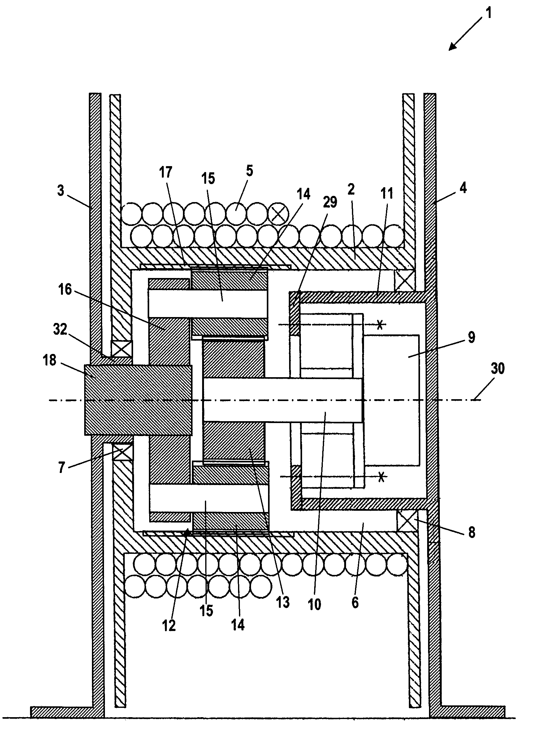
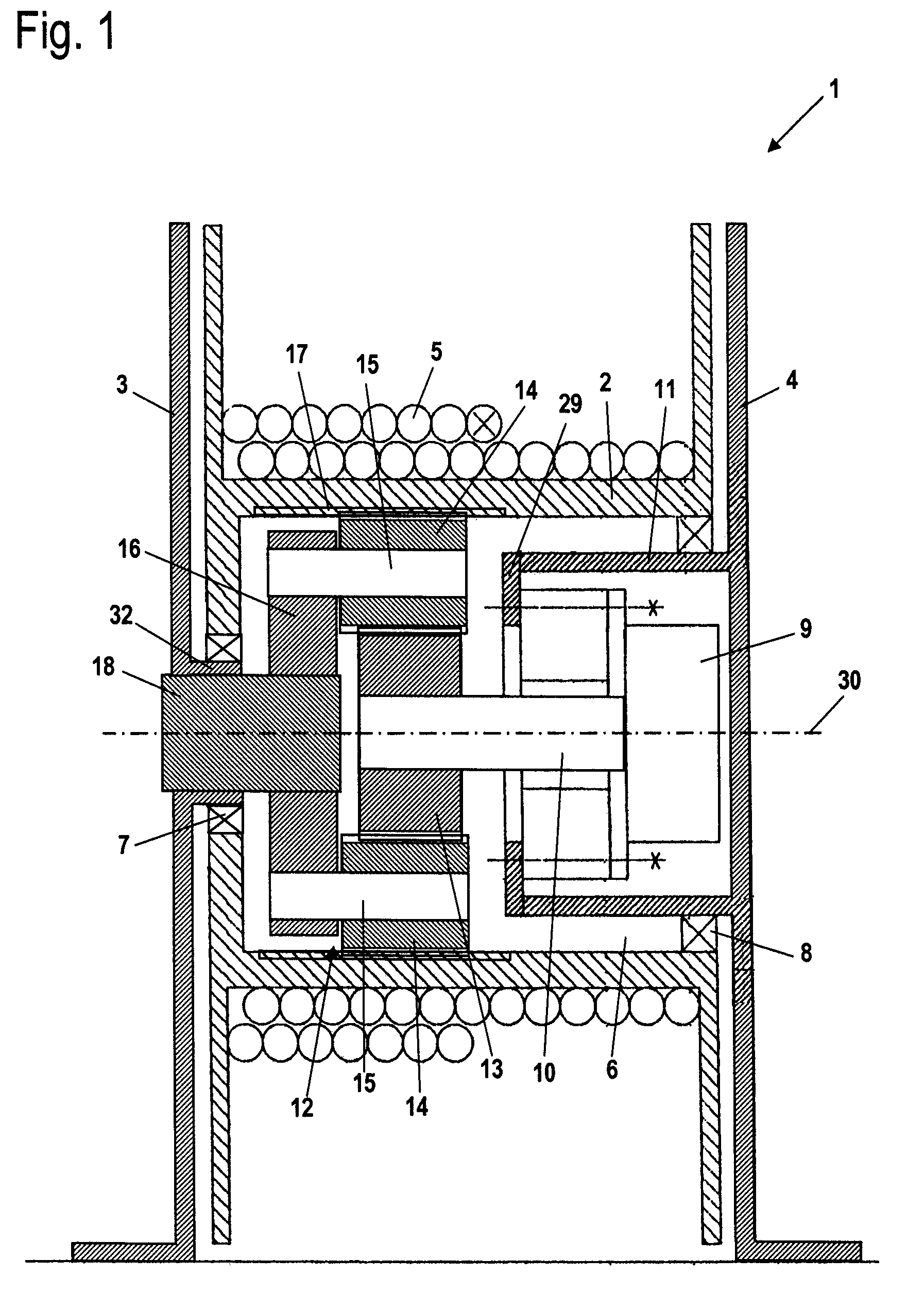
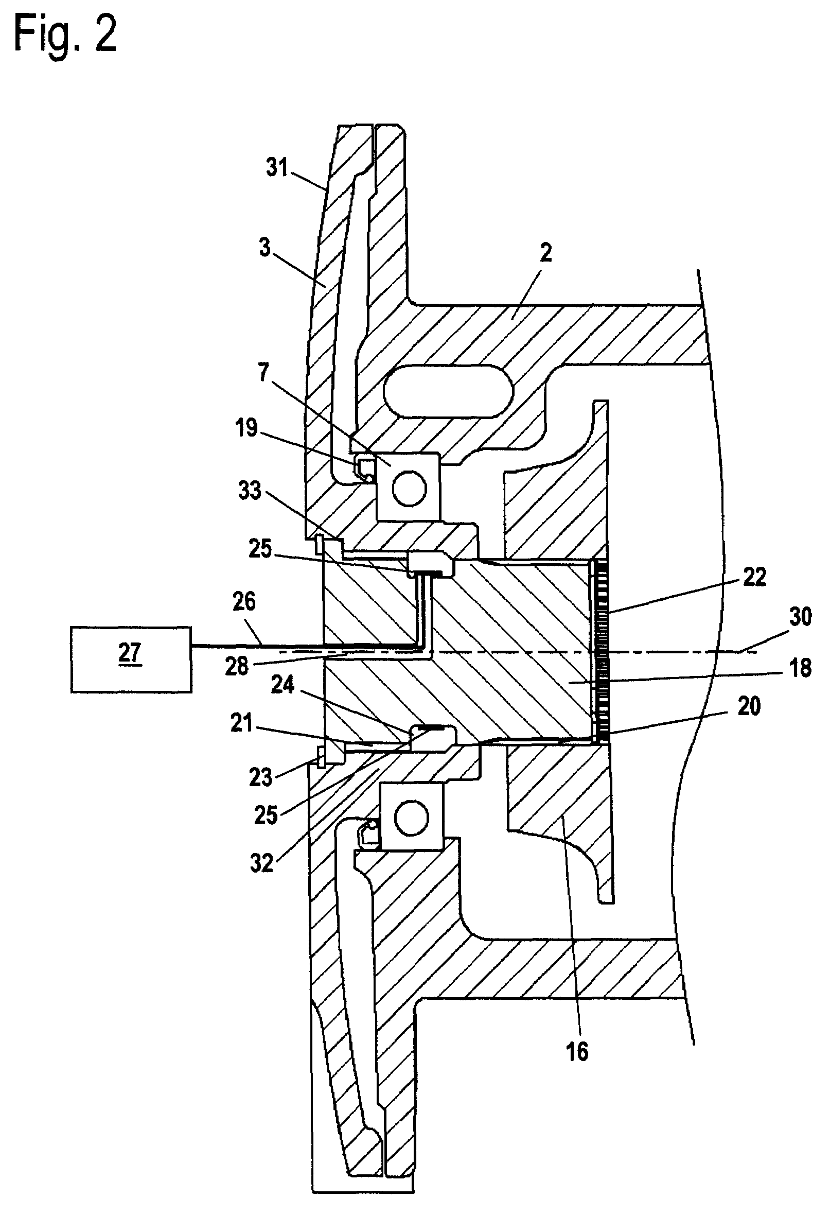
[0015]The rope winch 1 illustrated in FIG. 1 has two bearing supports 3, 4 between which a rope drum 2 is arranged. The rope drum 2 is supported so as to be rotatable about drive axis 30. A rope 5 is wound onto the rope drum 2 and, upon rotation of the rope drum 2 about its drive axis 30, depending on the rotational direction, is wound onto or removed from the rope drum 2. The rope drum 2 is supported on the bearing support 3 by means of a bearing 7 that rests on a collar 32 of the bearing support 3 projecting into the rope drum 2. As shown in FIG. 2, a seal 19 is arranged on the side of the bearing 7 facing the bearing support 3. The interior 6 of the rope drum 2 is open in the direction toward the bearing support 4. A receiving cup 11 is formed on the bearing support 4 and projects into the interior 6 of the rope drum 2. At its outer circumference a bearing 8 is arranged on which the other end of the rope drum 2 is supported.

[0016]A drive motor 9 is arranged in the receiving cup 1...


PUM


Abstract

A rope winch has at least one bearing support and a rope drum supported on the at least one bearing support so as to be rotatable about a drive axis. A drive motor and a gear connected to the drive motor are provided, wherein the drive motor drives the rope drum about the drive axis through the gear. At least one sensor that senses a load acting on the rope drum is provided. An exchangeably secured component that is exchangeable without dismounting the at least one bearing support is provided. The at least one sensor is arranged on the exchangeably secured component.

Description

BACKGROUND OF THE INVENTION[0001]The invention relates to a rope winch comprising a rope drum that is mounted on at least one bearing support so as to be rotatable about a drive axis and can be driven by a drive motor and a gear about its drive axis, wherein the rope winch has at least one sensor for detecting the load on the rope drum.[0002]German patent DE 195 12 103 C2 discloses a rope winch with a rope drum. For detecting the load on the rope drum, the rope winch is provided with torque sensors that are arranged in the interior of the rope drum on an outer circumference of a cup-shaped receptacle for the drive motor. In order to exchange the torque sensors, one of the bearing supports as well as the entire drive motor must be dismounted from the rope drum. This is very complicated so that repair or exchange of a torque sensor requires a high expenditure.SUMMARY OF THE INVENTION[0003]It is an object of the present invention to provide a rope winch of the aforementioned kind that ...

Claims


Application Information

Patent Timeline
Patent Type & Authority Patents(United States)
IPC IPC(8): B66D1/22
CPCB66D1/58B66D3/18
Inventor ROTZLER, JURGENWALZ, STEFFEN
Owner ROTZLER HLDG GMBH CO KG
Why Eureka
Try Eureka