Membrane apparatus for receiving samples

Inactive Publication Date: 2010-02-09
EPPENDORF AG
View PDF16 Cites 2 Cited by
  • Summary
  • Abstract
  • Description
  • Claims
  • Application Information

AI Technical Summary

Benefits of technology

[0011]According to an aspect, the membrane is circular. According to an aspect, the step and / or the deformed area extends / extend around the membrane, which specifically allows to fix the membrane more uniformly and to seal it more reliably.
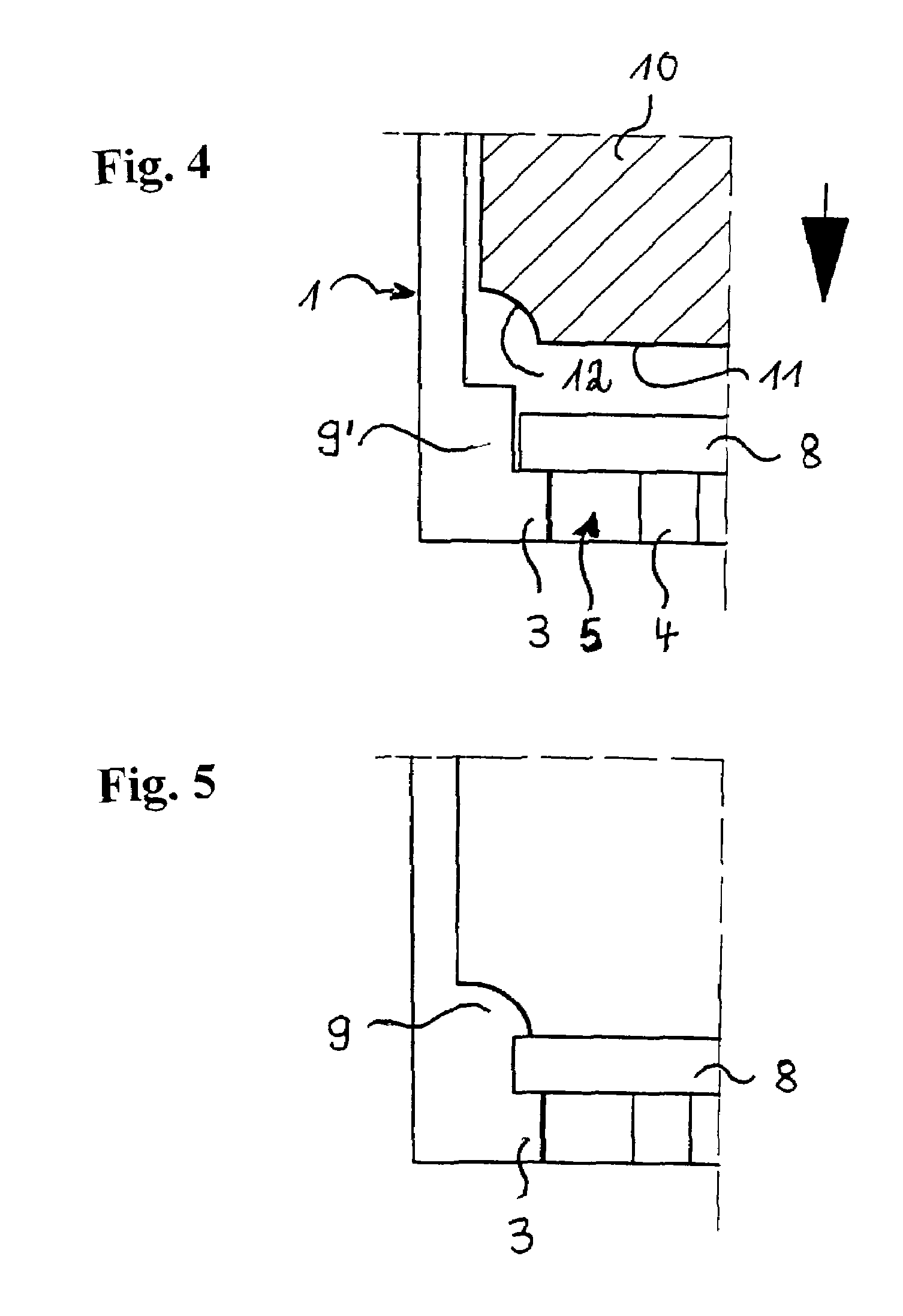
[0013]According to an aspect, the deformed area is manufactured from another step of the vessel which adjoins the step and the height of which exceeds the wall thickness of the membrane. This makes it possible to mount membranes having larger wall thicknesses in a vessel of the same type in the same manner. The extent to which the further step is deformed may be adapted to the wall thickness of the membrane. As a principle, however, it is also possible to fix membranes of different wall thicknesses while leaving unchanged the deformation of the further step if a different compression of the external membrane areas is not detrimental. Generally, the step may be defined by a further deformed area. However, it is preferred that it be formed already when the vessel is given its original shape, which can be done by injection molding, for instance, if the vessel is a plastic vessel.
[0018]According to an aspect, the deformation is a mechanical and / or thermal deformation. It is specifically in a thermoplastic material that the deformed are may be produced by thermal deformation or a combination of mechanical and thermal deformations. As a principle, a purely mechanical deformation may also be accomplished, e.g. by pressing, thread-cutting, etc. A flowable plastic (e.g. polytetrafluoroethylene) is also deformable mechanically without causing any destruction of the material structure.

Problems solved by technology

Moreover, fixing the membrane between the step and the deformed area may cause it to be sealed to the border.

Method used


Image

  • Membrane apparatus for receiving samples
  • Membrane apparatus for receiving samples
  • Membrane apparatus for receiving samples

Examples


Embodiment Construction

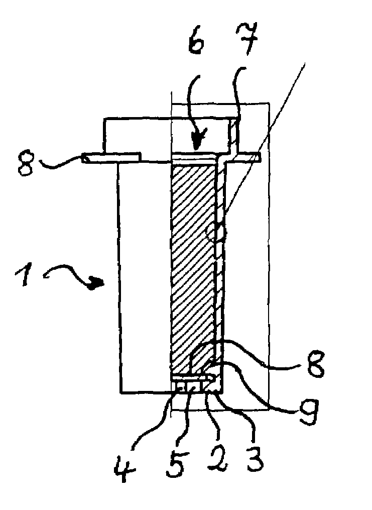
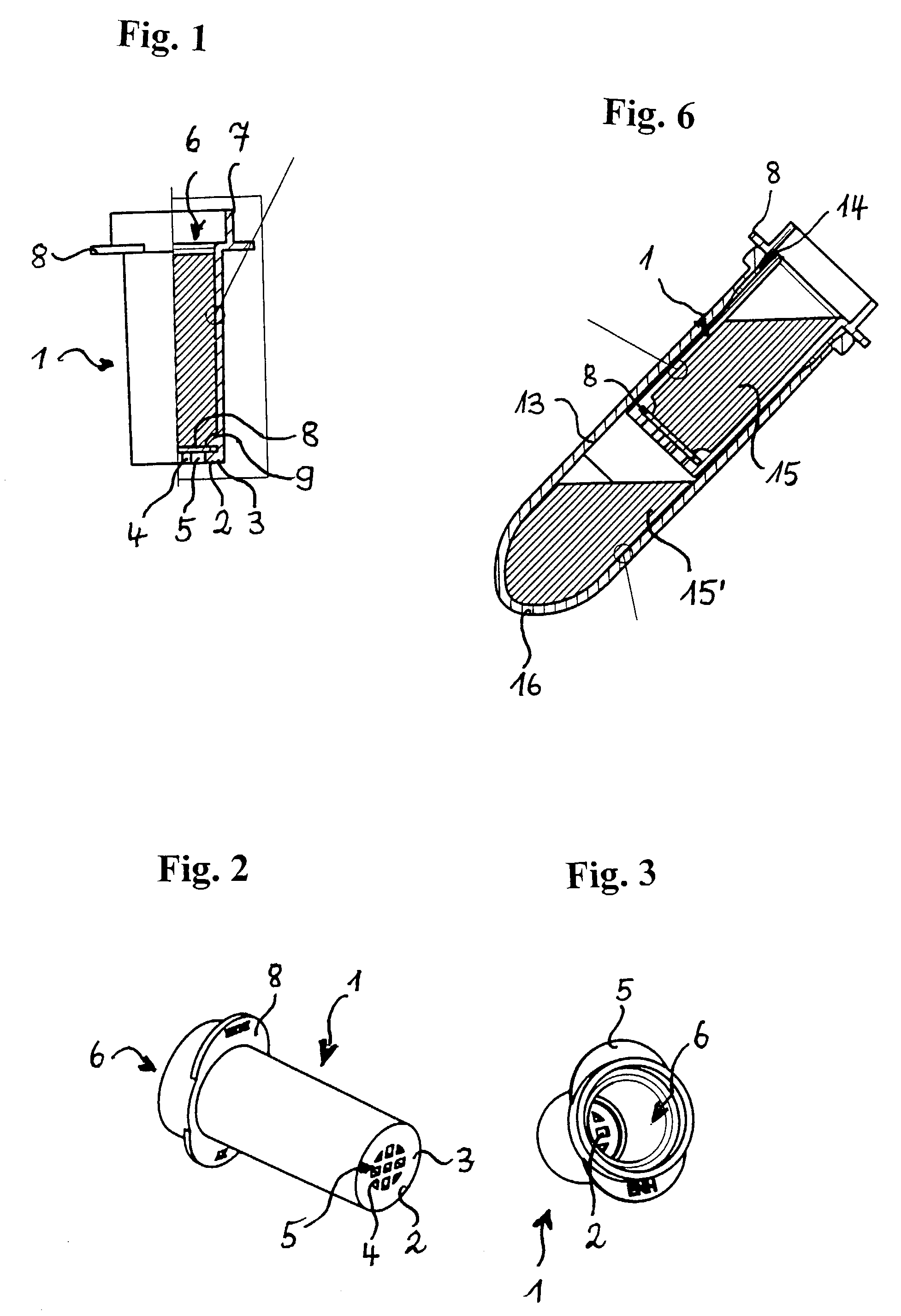
[0035]The centrifugal filtration vessel of FIGS. 1 through 3 is a cylindrical vessel 1 which has a bottom 2 which exhibits a border-sided step 3 and a grate-like structure 4 having apertures 5 in the centre.

[0036]Vessel 1 has a filling aperture 6 at the other end. Adjacent to the filling aperture 6 is an extension 7 which defines a receptacle for a stopper-like closure. Vessel 1 has an elliptical collar 8 at the outside at the level of filling aperture 6.

[0037]A circular membrane 8 made of a filtering material is arranged on bottom 2. This membrane is held at the border side between the circumferential step of bottom 2 and a deformed area 9 of the wall of vessel 1.

[0038]According to FIGS. 4 and 5, deformed area 9 has arisen from a further step 9′ which axially projects beyond step 3 in vessel 1 and the height of which exceeds the thickness of the membrane. A stamp 10 which is substantially cylindrical and includes a sonotrode and which has a circumferential fillet 12 at the border o...


PUM

PropertyMeasurementUnit
Areaaaaaaaaaaa
Metallic bondaaaaaaaaaa
Plasticityaaaaaaaaaa

Abstract

An apparatus for receiving samples, comprising at least one vessel having at least one aperture and a membrane covering the aperture which is held at the border side between a step and a deformed area of the vessel.

Description

BACKGROUND OF THE INVENTION[0001]1. Field of the Invention[0002]The invention relates to an apparatus which has at least one vessel including at least one membrane for receiving samples.[0003]2. Description of the Prior Art[0004]Apparatus of this type are known, especially for use at laboratories. For instance, those are centrifugal filtration vessels in the form of a small tube with a filtering membrane which closes a bottom-sided aperture. The centrifugal filter cartridge is inserted in the upper region of a centrifuging vessel and is supported by an outer step thereof at the border of the filling aperture of the centrifuging vessel. A sample liquid poured into the centrifugal filtration vessel is filtered by the membrane during centrifuging. The filtered liquid passes into the centrifuging vessel through the membrane and the aperture and the filtration residue is retained by the membrane. It is known to loosely place the membrane on top of a perforated bottom of the filtration ve...

Claims


Application Information

Patent Timeline
IPC IPC(8): B32B1/02B32B1/08B32B5/04B01D61/18B01D61/28B01D63/08B01D63/16B01L3/14B29C65/08B29C65/56
CPCB01D61/18B01D63/081B01D63/087B01D63/16B01L3/5021B29C65/568B29C66/545B01D61/28Y10T428/1314B01L2200/02B01L2200/12B01L2300/0681B01L2300/0851B01L2300/0861B29C65/08B29C66/8322Y10T428/131Y10T428/1359Y10T428/1352Y10T29/49908Y10T428/139Y10T428/13B29C66/71B29K2081/06B29K2077/00B29K2023/12B29K2001/00B29C66/7234
Inventor SCHWARZWALD, DETLEF
Owner EPPENDORF AG
Why Eureka
Try Eureka