Acoustic echo cancellation

a technology of acoustic echo and cancellation, applied in the field of multiple channel acoustic echo cancellation, can solve the problems of not being able to achieve a convergent set of filters, major obstacles to be overcome, and less advanced existing solutions, so as to reduce the number of filter operations

Inactive Publication Date: 2010-02-09
BRITISH TELECOMM PLC
View PDF22 Cites 20 Cited by
  • Summary
  • Abstract
  • Description
  • Claims
  • Application Information

AI Technical Summary

Benefits of technology

[0019]This exemplary embodiment of the invention is an adaptation of the monophonic LMS process and avoids multiple updates to two of more echo path estimates, such as ĥ1 and ĥ2, and reduces the number of filter operations required when compared with existing stereo echo cancellation processes, such as ĥ1* x1 and ĥ2 * x2. Additionally, this embodiment of the invention uses the spatialisation parameters in the adaptive process, unlike existing stereo echo cancellation processes. The LMS update is modified to take into account the spatialisation parameters that are used to update the aggregated echo path estimate each time the spatialisation changes. After the Nth spatialisation change, (where N is the number of channels in the system), the aggregated echo path estimate converges towards the aggregate echo path for future changes in spatialisation. Prior to the Nth spatialisation change the process converges to a local solution for the aggregated echo path estimate so that some echo signal reduction is still given in the learning stage of the process.

Problems solved by technology

However, for stereophonic and multiple channel systems, existing solutions are far less advanced with some major obstacles yet to be overcome.
With existing adaptive filter processes it is not possible to achieve a convergent set of filters such that
However, as the signals x1 and x2 are inherently highly correlated in a teleconferencing system, techniques that exploit the small decorrelated features in the signals have poor performance in anything but ideal conditions.
However, although adding noise in this manner does improve the convergence, the noise has to be added at such a level that it is undesirably audible.

Method used


Image

  • Acoustic echo cancellation
  • Acoustic echo cancellation
  • Acoustic echo cancellation

Examples


Embodiment Construction

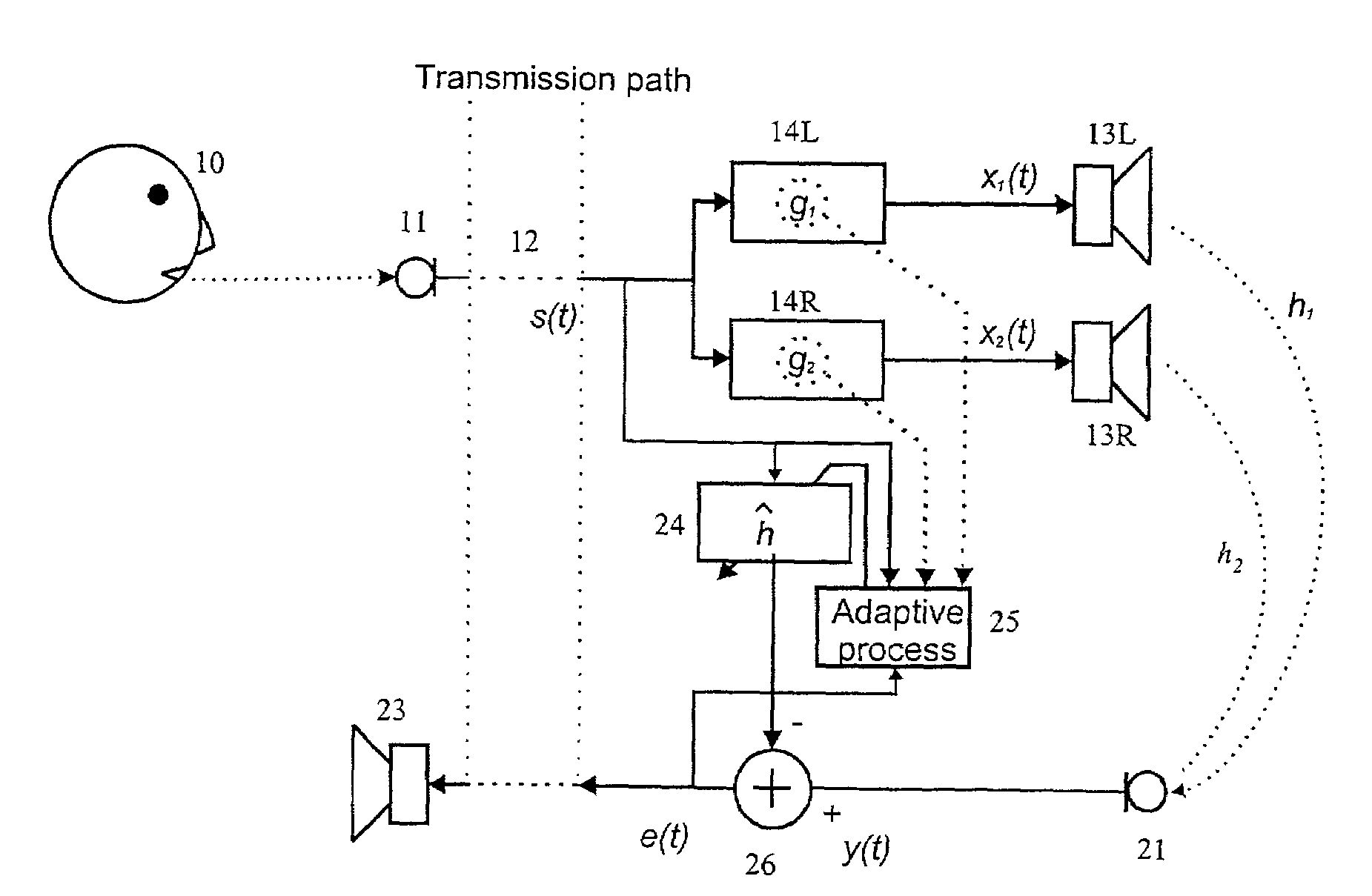
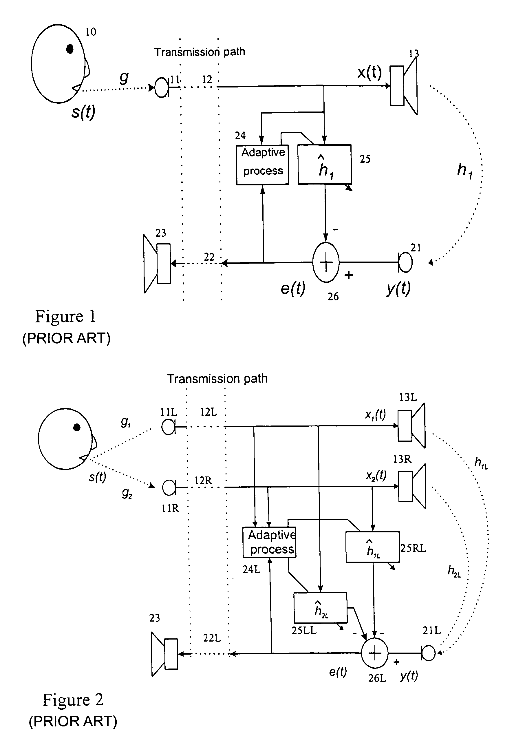
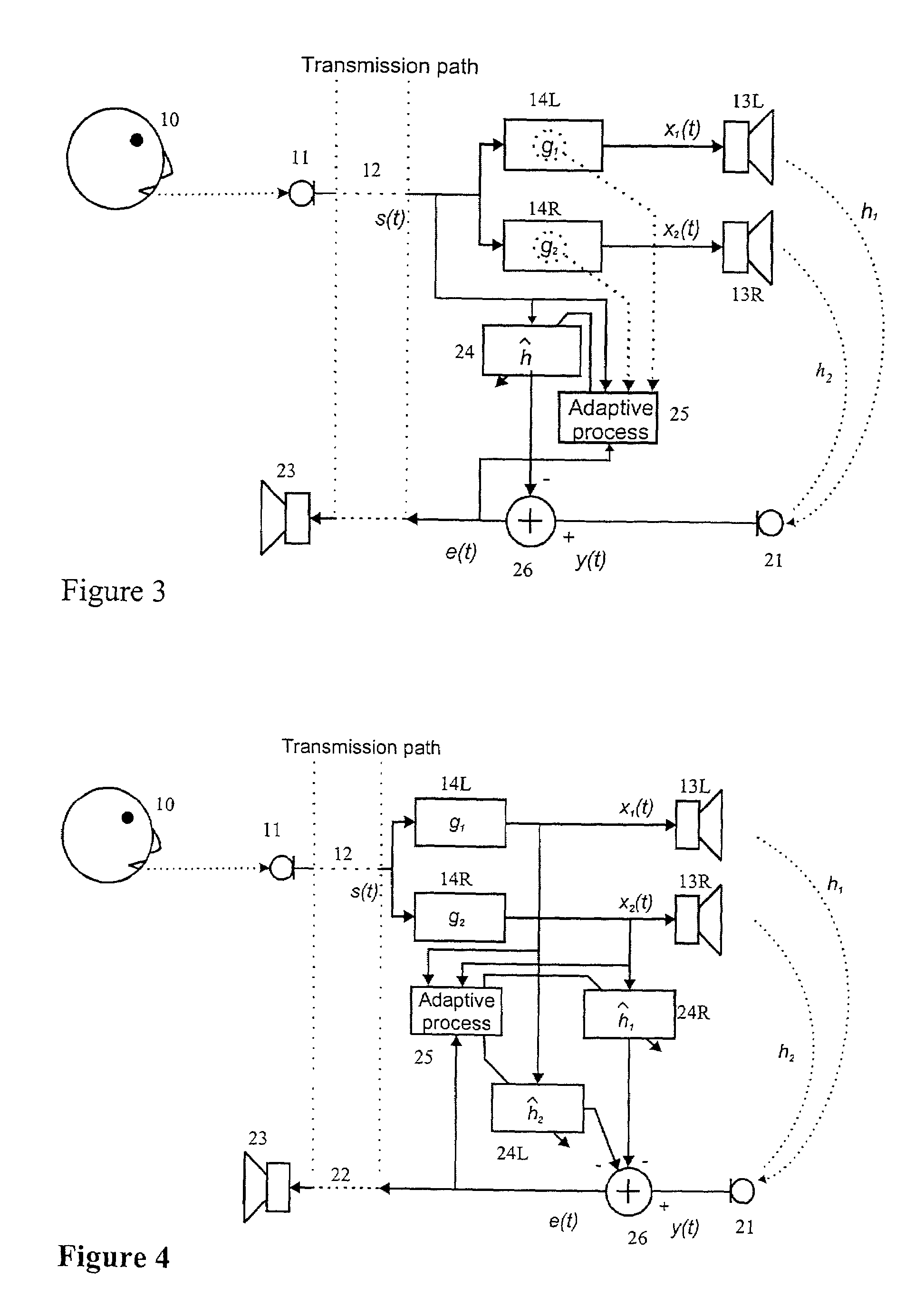
[0029]The monophonic system illustrated in FIG. 1 comprises an input path 12 connected to the source (microphone 11 and speaker 10) of the original signal s(t). This signal s(t) is modified by the transmission path 12 to generate a loudspeaker signal x(t) which is fed to the loudspeaker 13. The return path consists of a microphone 21, return transmission path 22 and loudspeaker 23. An acoustic path h1 exists between the loudspeaker 13 of one path and the microphone 21 of the other path. Hence, some sound originating with the speaker 10 will be returned to the loudspeaker 23 and will be heard by the speaker 10 as echo. This effect can be intrusive, especially as the transmission paths 12, 22 can introduce delays, so an echo cancellation processor 24, 25, 26 is installed to eliminate this signal. An adaptive processor 24 compares the signal e(t) to be transmitted over the return path 22 with the signal x(t) arriving over the input path 12 and identifies correlations between them. This...


PUM


Abstract

A multiple channel steered spatialized signal is generated from a signal input modified according to respective spatialization gain functions to generate a plurality of audio channels. An echo cancellation signal is applied to a return path using a combined spatialization and echo path estimate. The estimate is derived from the gain functions applied to the respective channels. When the gain functions applied in the respective channels are changed, for instance to represent a different apparent position of the sound source, a new estimate of the echo paths is generated, based on a previous estimate of the echo path and on the new gain functions.

Description

BACKGROUND[0001]1. Technical Field[0002]This invention relates to a method for multiple channel acoustic echo cancellation (AEC), applicable to systems that derive a multi-channel spatialised signal from a monophonic signal, each channel of which is applied to a respective member of an array of loudspeakers at differing gains to give the percept or audible illusion of directionality. This class of spatialised signal will be termed here as steered mono. A steered mono system uses two or more gain elements to represent the spatialisation, which is mapped to a panning processor to generate corresponding loudspeaker outputs. In the embodiments to be described, a two-channel stereophonic signal is used, with two loudspeakers—a system known as “stereo from steered mono” (SSM), but the principles of the invention can be applied to systems with more than two channels. The invention has application in teleconferencing systems where each talker's voice is artificially given spatial positionin...

Claims


Application Information

Patent Timeline
Patent Type & Authority Patents(United States)
IPC IPC(8): H04B3/20H04R3/02G10L21/0208G10L21/0232H04B7/015H04M1/60H04M9/08
CPCH04M9/082
Inventor REED, MARTINHAWKSFORD, MALCOLM JOHN
Owner BRITISH TELECOMM PLC
Why Eureka
Try Eureka