Locking device

a technology of locking device and gear shift lever, which is applied in the direction of mechanical control device, process and machine control, instruments, etc., can solve the problems of large installation space, complicated shape of components, and inability to accurately indicate the shift position of gear shift lever, etc., to achieve reliable and uniform, small space, and simple design

Active Publication Date: 2010-02-16
ZF FRIEDRICHSHAFEN AG
View PDF7 Cites 13 Cited by
  • Summary
  • Abstract
  • Description
  • Claims
  • Application Information

AI Technical Summary

Benefits of technology

[0007]The object of the present invention is consequently to provide a locking device with a centering device, which has a compact design, requires only a small space for its installation and contains components of a simple design. Furthermore, the centering device shall guarantee reliable and uniform centering with a uniform force distribution.
[0008]This object is accomplished according to the present invention with a locking device with a centering device provided between a pin and a bracket is characterized according to a first embodiment in that the centering device has at least one elastically deformable ring, which is arranged completely within a recess provided in a bracket between the pin and the bracket. The elastically deformable ring is arranged displaceably within the recess and has a surface with a cross section that tapers against the direction of the force of a compression spring acting axially on the pin and is in contact with a complementary surface on the pin. Under the action of the axially acting spring force, the surface of the elastically deformable ring slides on the complementary surface of the pin and the ring expands. The ring is in contact now with the inner surface of the recess and thus compensates the clearance between the pin and the recess and centers the pin in relation to the longitudinal axis of the recess.
[0010]In a preferred embodiment, the elastically deformable rings are designed as slotted rings with at least one continuous slot, which is arranged axially or obliquely in relation to the longitudinal axis of the recess and completely or partially severs the ring. Such a locking device with a centering device is characterized by a compact design requiring little space for its installation. In particular, the radial extension as well as the axial extension of the locking device can remain limited to a minimum. Thus, the diameter of the recess needs to be only slightly larger in the first embodiment than the diameter of the pin. The compact design is facilitated by the simple design of the elastically deformable rings, especially the slotted rings, which are standard components, as a result of which additional cost savings are achieved.
[0011]In an especially advantageous embodiment, the tapering surface of the elastically deformable ring or rings has a conical shape. As a result, favorable force distribution is obtained especially for components of a radial design, especially if the spring load generated, for example, by an inserted compression spring, acts directly on the elastically deformable ring. At the other end, the compression spring is supported on the pin or the bracket. The slotted rings, in particular, slide simply over the conical surfaces and can simply expand or contract correspondingly. The load is advantageously supported and transmitted over a large area, as a result of which the pin is relieved and the risk of premature wear is avoided.
[0013]The use of slotted rings makes it, moreover, possible to select the material relatively freely for the combination of pin, bracket and elastically deformable ring. Thus, the slotted ring, in particular, may be manufactured from a plastic or, for example, a metallic material, for example, a spring steel, or a very hard plastic. The pin as well as the bracket are advantageously manufactured from a plastic for reasons of low weight, but it is also possible to use other materials, such as metallic materials. Furthermore, the use of elastically deformable rings makes it possible to freely select the location of the centering device within the recess, so that there are certain possibilities of variation here, for example, for the optimal determination of lever lengths.

Problems solved by technology

Due to tolerances related to the design and manufacture, the mounting of the movable parts of the locking devices, especially a locking pin, has a clearance, which leads to an inaccurate and fuzzy indication of the shift position by the gearshift lever.
Furthermore, this clearance may lead to an undesired noise generation during travel.
The components that have a complicated shape and require much space for their installation are especially disadvantageous in the embodiment according to WO 02 / 061 522.
Furthermore, clamping does not necessarily take place for the centering over the entire circumference of the pin, but in a punctiform manner only and over a relatively small pressing area, which may lead to premature wear phenomena in the form of pressure marks and furrows on the pin in the unfavorable case.
Selection from among the possible materials that can be used is thus greatly limited.
Another essential disadvantageous aspect of the embodiment according to WO 02 / 061 522 is the possible squeezing of the sleeve during the shifting operation or in case of abuse.
The shifting forces act on the pin at right angles to the longitudinal axis thereof during the shifting operation, as a result of which the shifting forces are transmitted completely via the sleeve, especially in case of abuse, and there is a risk of damage to the sleeve.

Method used


Image

  • Locking device
  • Locking device
  • Locking device

Examples


Embodiment Construction

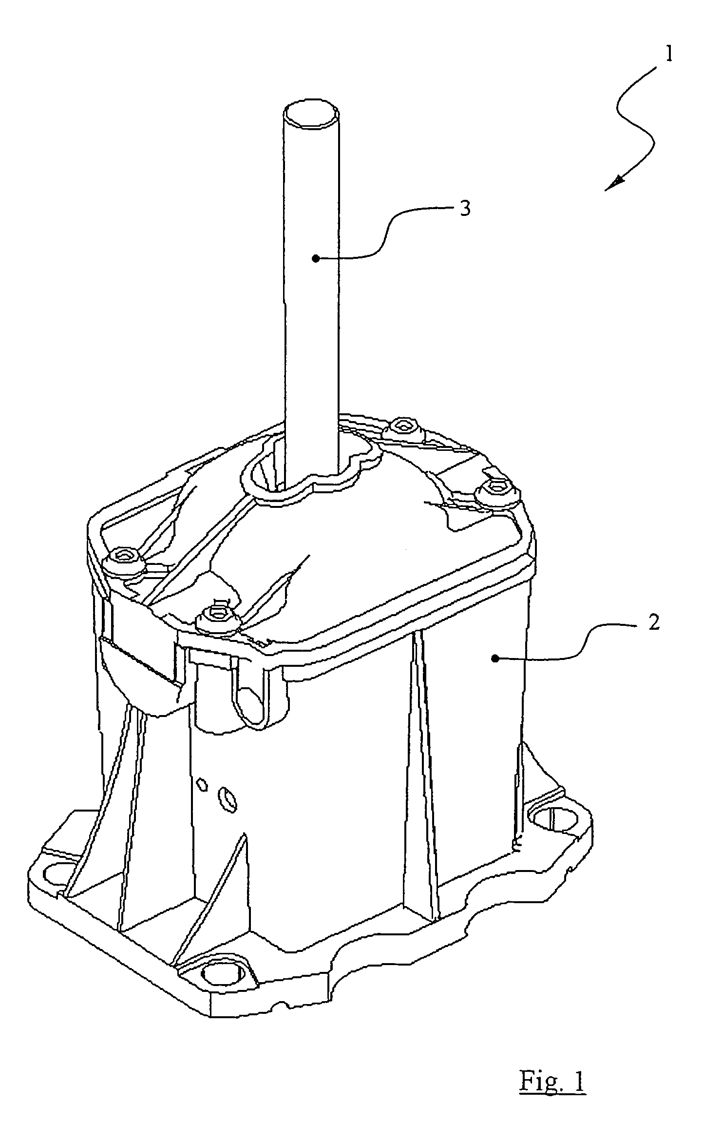
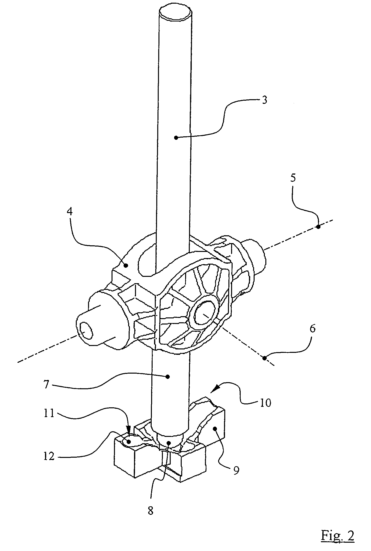
[0025]Referring to the drawings in particular, FIGS. 1 and 2 show an exemplary embodiment of a shifting device 1 for actuating a transmission in motor vehicles. A gearshift lever 3 is mounted in a gearshift housing 2 connected rigidly to the vehicle body pivotably about a first pivot axis 5 and a second pivot axis 6 by means of a swivel joint 4. A bracket 7, which is rigidly connected to the gearshift lever 3 and has a one-part design together with the gearshift lever 3 here, in which said gearshift lever a movable pin 8 is arranged, is provided at the lower part of the gearshift lever 3, which said part is located in the gearshift housing 2. Together with a contour 9, which is rigidly connected to the gearshift housing 2, the bracket 7 and the pin 8 form the locking device 10. The contour 9 has a guide groove 11 with a contact surface 12, which is in contact with the pin 8.

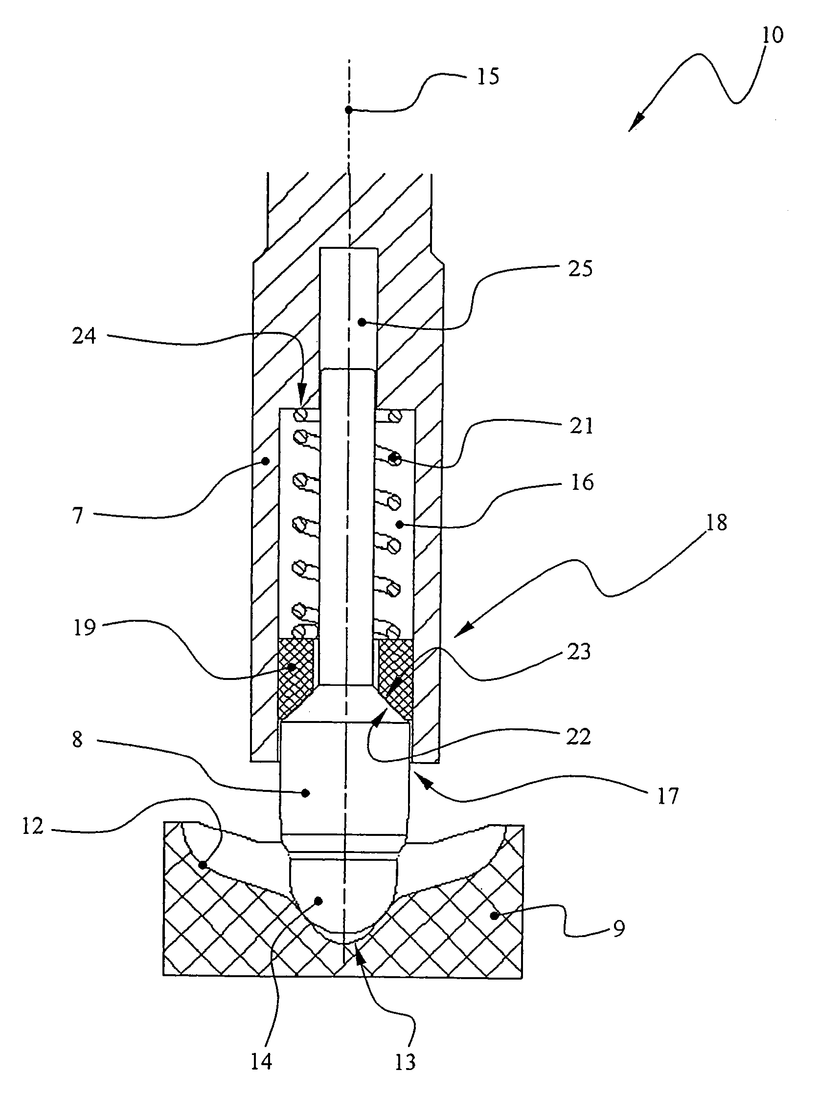
[0026]A first exemplary embodiment of the inner design of the locking device 10 is shown in FIGS. 3 and 4. The...


PUM


Abstract

A locking device (10) includes an adjustable bracket (7) provided with a recess (16), a stationary contour (9) with a contact surface (12), a pin (8), which is arranged movably in the recess (16) and on which an axial spring force generated by a compression spring (21) acts. A pin head (14) projects from the recess (16) of the bracket (7) and has a contact pair with the contact surface (12). At least one centering device (18) is provided between the pin (8) and the bracket (7). The locking device has a centering device (18), which has an elastically deformable ring (19). The ring (19) is arranged between the pin (8) and the bracket (7) within the recess (16) and is displaceably arranged within the recess (16). The ring (19) has a surface (22) with a cross section tapering against the direction of the force of the compression spring (21). The surface is in contact with a complementary surface (23) at the pin (8).

Description

CROSS REFERENCE TO RELATED APPLICATIONS[0001]This application is a United States National Phase application of International Application PCT / DE 2004 / 002116 filed Sep. 23, 2004 and claims the benefit of priority under 35 U.S.C. § 119 of German Application DE 103 44 287.1 filed Sep. 23, 2003, the entire contents of which are incorporated herein by reference.FIELD OF THE INVENTION[0002]The present invention pertains to a locking device with an adjustable bracket, in which a recess is provided for a pin on which a spring force acts. The head of the pin projects from the recess and is in contact with a contact surface at a stationary contour.BACKGROUND OF THE INVENTION[0003]Such locking devices are used, for example, in shifting devices for actuating transmissions in motor vehicles in order to indicate the shift positions selected by the driver by means of a gearshift lever. The gearshift lever is fixed in the shift positions by means of a locking device in relation to a gearshift housin...

Claims


Application Information

Patent Timeline
Patent Type & Authority Patents(United States)
IPC IPC(8): G05G1/04F16H61/24G05G5/06
CPCF16H61/24G05G5/06B60Q1/1469F16H2061/243Y10T74/20612Y10T74/20666Y10T74/20122Y10T74/20128G05G5/00B60K20/00
Inventor GIEFER, ANDREASMEYER, JORG
Owner ZF FRIEDRICHSHAFEN AG
Why Eureka
Try Eureka