Dynamic real-time quality management of packetized communications in a network environment

Inactive Publication Date: 2010-02-16
AVAGO TECH INT SALES PTE LTD
View PDF35 Cites 10 Cited by
  • Summary
  • Abstract
  • Description
  • Claims
  • Application Information

AI Technical Summary

Benefits of technology

[0020]By monitoring the packetized communications from end-to-end, the method can intelligently manage the selected coding scheme and routing of the packetized communications. For example, in one instance, the processor communicates with a far-end terminal to identify an appropriate coding scheme. These coding schemes may include, but are not limited to audio and / or video coding schemes such as Huffman encoding, ITU-T G.711, u-law, A-law, CCITT G.721, CCITT G.723, ITU-T G.726, ITU-T G.723.1, ITU-T G.723.1A, ITU-T G.729, ITU-T G.729A, ITU-T G.729AB, ITU-T G.729E, ITU-T G.728, ITU-T G.722, ITU-T G.722.1, ITU-T G.722.2, GSM-EFR, GSM AMR, IMA / DYI ADPCM, Microsoft ADPCM, LPC-10E, CELP GSM 06.10, shorten, Real Audio, 15 MPEG, ACE and MACE.
[0022]This information allows the processor to select the route the communications take by choosing which network segments are used to route the communications or which AP is servicing the communication. In the case of the latter, the APs are queried to determine the expected service quality level from each AP. Then, the WLAN terminal registers with a new servicing AP when the expected service quality level to be provided by the new servicing AP exceeds the expected service quality level provided by the servicing AP by a predetermined service quality level.

Problems solved by technology

These impediments may take the form of coding problems in which case an appropriate coding scheme is selected and implemented.

Method used


Image

  • Dynamic real-time quality management of packetized communications in a network environment
  • Dynamic real-time quality management of packetized communications in a network environment
  • Dynamic real-time quality management of packetized communications in a network environment

Examples


Embodiment Construction

[0044]Preferred embodiments of the present invention are illustrated in the figures, like numerals being used to refer to like and corresponding parts of the various drawings.

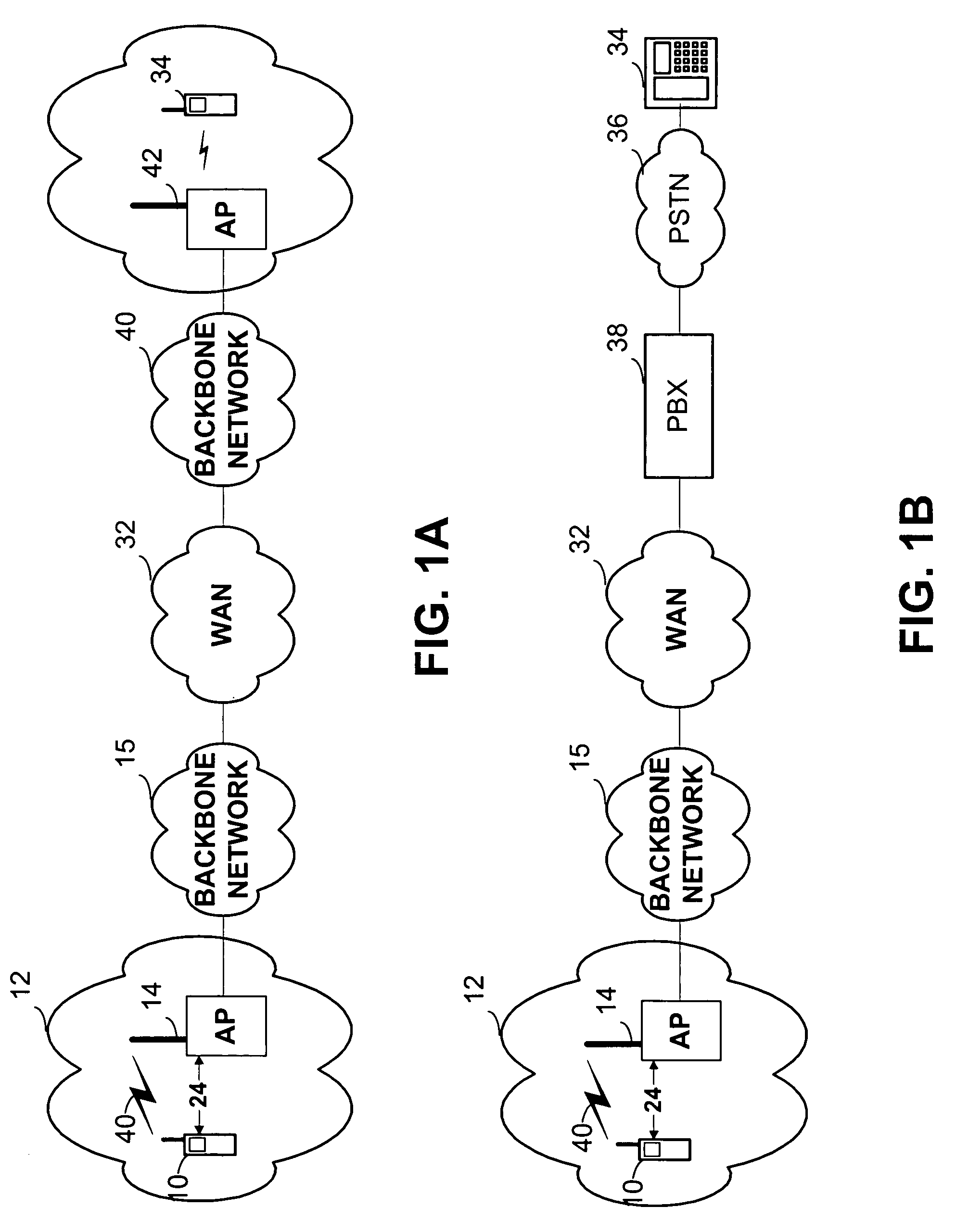
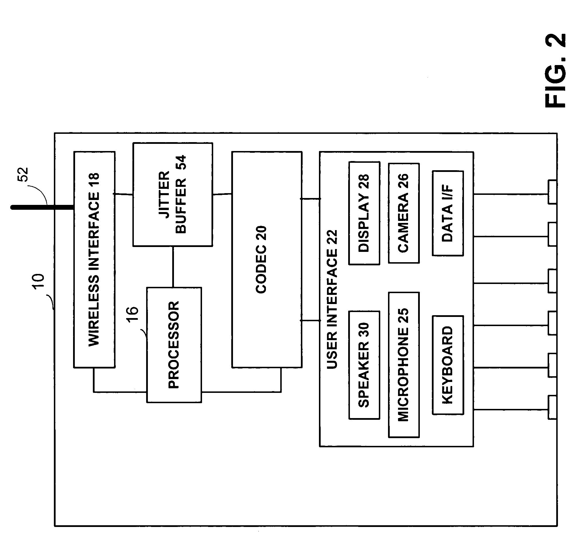
[0045]FIG. 1A provides a diagram illustrating a wireless terminal 10 wirelessly coupled to WLAN 12 through AP 14. FIG. 2 further details wireless terminal 10. Processing unit 16 within wireless terminal 10 couples to and directs the functions of wireless interface 18 that communicatively couples to AP 14. Additionally, processing unit 16 couples to and directs programmable COder / DECoder (CODEC) 20 to convert user information or communications received at user interface 22 into packetized communications. User interface 22 may take the form of a microphone 25, camera 26, or other like device to receive audio and / or visual input from a user. Additionally, the user interface 22 may include a display 28, speaker 30, or other like device to present audio and / or visual information to the user. Packetized communication...


PUM


Abstract

The present invention provides a dynamic real-time quality management of packetized communications in a network environment. Packetized communications are monitored by and exchanged between wireless Access Points (APs) and wireless terminals or by quality monitoring modules located within network segments or at network vertices. The processing unit analyzes the packetized communications to identify communication signatures associated with the packetized communications. The processor then uses these signatures to identify network impediments to the exchange of the packetized communications. These impediments may take the form of coding problems in which case an appropriate coding scheme is employed by the programmable COder / DECoder (CODEC) to convert incoming packetized communications to incoming user communications, and outgoing user communications to outgoing packetized communications. These impediments may also take the form of communication problems along and between the various network segments. In these cases, the processor may choose a more appropriate communication pathway with which to route the packetized communications.

Description

PROVISIONAL PRIORITY CLAIMS[0001]The present U.S. Utility Patent Application claims priority pursuant to 35 U.S.C. §119(e) to the following U.S. Provisional Patent Application which is hereby incorporated herein by reference in its entirety and made part of the present U.S. Utility Patent Application for all purposes:[0002]1. U.S. Provisional Application Ser. No. 60 / 472,647, entitled “Method for and off of a Telephone Call between Two Different Wireless Networks,”, filed May 22, 2003, pending.TECHNICAL FIELD OF THE INVENTION[0003]The present invention relates generally to communication networks supporting multimedia packetized communications, and more particularly to a system for managing the quality of service provided by a wireless local area network.BACKGROUND OF THE INVENTION[0004]Communication technologies that network electronic devices are well known. Examples include wired packet data networks, wireless packet data networks, wired telephone networks, and satellite communicat...

Claims


Application Information

Patent Timeline
Patent Type & Authority Patents(United States)
IPC IPC(8): G01R31/08H04L12/28H04L12/56H04L12/66H04M7/00H04W24/00H04W28/04H04W40/02H04W84/12H04W88/06H04W88/08
CPCH04L47/10H04L47/11H04L47/14H04L47/2416H04L47/2433H04L47/2458H04M7/006H04W88/06H04W24/00H04W28/04H04W40/02H04W84/12H04W88/08H04W28/0284H04W8/04
Inventor BYE, RICHARD
Owner AVAGO TECH INT SALES PTE LTD
Why Eureka
Try Eureka