Kitchen appliance having a floating glass panel

Inactive Publication Date: 2010-02-23
MAYTAG
View PDF22 Cites 37 Cited by
  • Summary
  • Abstract
  • Description
  • Claims
  • Application Information

AI Technical Summary

Problems solved by technology

Additionally, trim pieces fit between the glass panel and the appliance door, such that the spacers are not even visible when viewing the kitchen appliance from angled side views.

Method used


Image

  • Kitchen appliance having a floating glass panel
  • Kitchen appliance having a floating glass panel
  • Kitchen appliance having a floating glass panel

Examples


Embodiment Construction

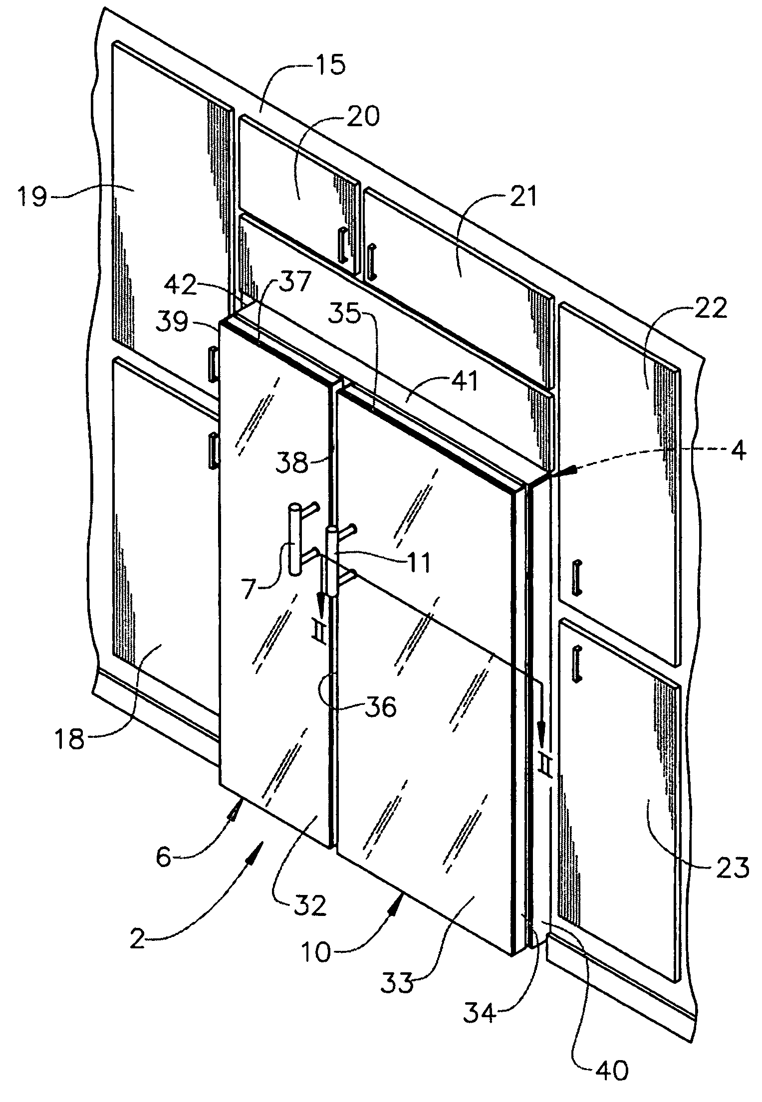
[0017]With initial reference to FIG. 1, a kitchen appliance, which is shown to be a refrigerator constructed in accordance with the present invention, is generally indicated at 2. Refrigerator 2 includes a cabinet 4 and is shown to include a freezer door 6, which is pivotally mounted to cabinet 4 and has an associated handle 7, and a fresh food door 10, which is also pivotally mounted to cabinet 4 and has an associated handle 11. In a manner known in the art, freezer and fresh food doors 6 and 10 selectively provide access to corresponding freezer and fresh food compartments (not shown). In the embodiment depicted, refrigerator 2 is of the recessed-type such that, essentially, only a small portion of refrigerator 2 projects forward of an associated wall 15, as well as a plurality of cabinets generally indicated at 18-23. It should be understood that refrigerator 2 could be arranged substantially flush with wall 15 and cabinets 18-23, may be bordered by cabinets only on one side, or ...


PUM


Abstract

A glass panel assembly for kitchen appliances includes a glass panel and a plurality of spacers. The spacers are mounted to an outer surface of the appliance and an inner surface of the glass panel. Preferably, the spacers are adhesively secured to the glass panel and are not visible when viewing the kitchen appliance from the front. Trim pieces fit between the glass panel and the appliance door to cover and further hide the spacers from view. The glass panel can be mounted to any outer surface of the appliance such as an appliance door, side walls or even a top wall. The particular construction of the spacers, in combination with the trim pieces creates an illusion that glass panel appears to float relative to the appliance.

Description

BACKGROUND OF THE INVENTION[0001]1. Field of the Invention[0002]The present invention pertains to the art of kitchen appliances and, more particularly, to providing a kitchen appliance with one or more decorative glass panels.[0003]2. Discussion of the Prior Art[0004]Attaching a decorative façade to kitchen appliances is well known in the art. The decorative façade allows the appliance to “tie-in” to overall kitchen décor. The decorative façade can take on a variety of forms from something as simple as a coat of paint to made-to-order wooden panels that match adjacent cabinetry. In many cases, the decorative panel takes the form of a replaceable plastic or metal sheet that is mounted to a door of the appliance by peripheral trim components.[0005]In addition to mounting wood, plastic or metal panels to appliance doors, it also known to employ glass panels. Typically, a glass panel is secured to an appliance through trim pieces in a manner similar to that employed with plastic and met...

Claims


Application Information

Patent Timeline
Patent Type & Authority Patents(United States)
IPC IPC(8): A47G29/00
CPCF25D23/10F25D2400/18
Inventor CROMPTON, EDWARDMYERS, JOHN PHILLIP
Owner MAYTAG
Why Eureka
Try Eureka