
Medical needle having a closed tip

a technology of medical needles and needle tips, which is applied in the field of medical needles, can solve the problems of inhibit hindering the flow of blood through the needle, and shortening the so as to facilitate blood transfer, promote the extension of the useable life of the shunt, and minimize the damage of the shunt

Inactive Publication Date: 2010-02-23
ATIL PLARIDEL CERNA
View PDF19 Cites 15 Cited by
  • Summary
  • Abstract
  • Description
  • Claims
  • Application Information

AI Technical Summary

Benefits of technology

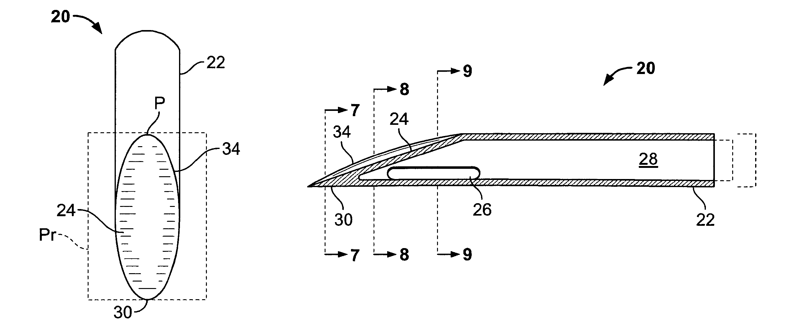
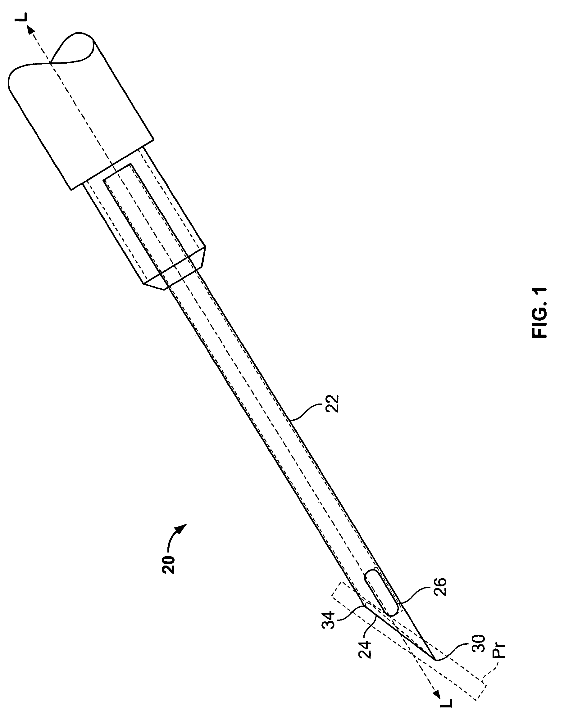
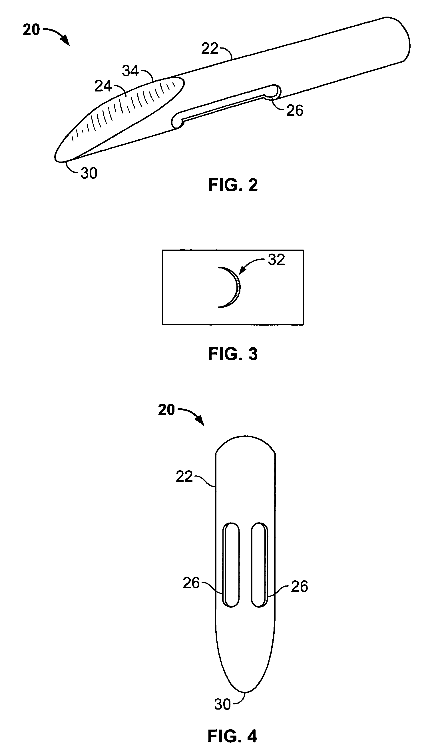
"The invention provides a needle with a closed tip that minimizes tissue damage during penetration. The needle has a tubular side wall with an internal bore and an end wall angled relative to the needle's longitudinal axis. The closed tip has a rounded top profile and an acutely angled side profile. The needle can have one or more openings, which can be positioned at the end wall or along the side wall. The needle can be used in dialysis treatment to minimize damage to the shunt and promote its extended useable life. The invention reduces the amount of debris that would otherwise enter the blood stream, which can help prevent pulmonary hypertension in patients with chronic hemodialysis treatments."

Problems solved by technology

Although such open-end needles are generally effective for fluid transfer, shortfalls exist.
For example, such needles can remove tissue when used (i.e., coring tissue), which, in dialysis treatment, can create problems with clotting and can inhibit the life of the shunt.
Also, during treatment, cored tissue can hinder the flow of blood through the needle.
Moreover, at the point of insertion, current needles commonly create circular penetration marks on the patient, which can impede healing.

Method used


Image

  • Medical needle having a closed tip
  • Medical needle having a closed tip
  • Medical needle having a closed tip

Examples


second embodiment

[0039]With reference now to FIGS. 10-13, a needle 50 is shown. The needle 50 is similar to the needle 20 of FIG. 1, though the configurations of the openings differ. In this embodiment, a first opening 52 defined by the end wall 54 and a second opening 56 defined by the side wall 58. The first opening is positioned near proximal point (P) of the end wall. The rim 60 of the needle is raised relative the first opening, as viewed from the side (FIG. 13). The second opening is approximately 180 degrees about the needle relative to the first opening. The openings are sized to facilitate flow through the internal bore 62 of the needle and are sufficiently positioned to inhibit coring of tissue.

third embodiment

[0040]With reference now to FIGS. 14-17, a needle 70 is shown. In this embodiment, the needle provides a single opening 72 defined by the side wall 74, proximate to the closed tip 76. The opening is approximately 180 degrees about the needle relative to the end wall 81. The area of the opening substantially equals the cross-sectional area of the internal bore 78. In use, the needle preferably is inserted at an angle with the opening facing downward.

fourth embodiment

[0041]With reference now to FIGS. 18 and 19, a needle 80 is provided. In this embodiment, the needle defines in a closed tip 82 having two side edges 84 that terminate in a point 86. An end wall 88 of the needle includes a flat portion 90 proximate to the point and a concave portion 92. The needle further defines an opening 94 spaced from the closed tip.


PUM


Abstract

A needle is provided, having a closed tip configured to minimize tissue damage from penetration of the needle. The needle includes a tubular side wall defining an internal bore. The needle further includes an end wall angled relative to the needle's longitudinal axis and disposed at the distal end of the needle. The needle defines a distal opening spaced from the closed tip, providing access to the internal bore to facilitate fluid transfer. Preferably, the needle is configured to create a crescent-shaped penetration mark. The number and positioning of openings can be varied across embodiments of the invention, while maintaining a closed tip. For example, in certain embodiments, the needle comprises two distal openings defined by the side wall. A distal opening can also be provided by the end wall singly or in combination with additional distal openings.

Description

BACKGROUND OF THE INVENTION[0001]This invention relates generally to medical needles for delivery and extraction of fluid and, more particularly, to such medical needles having a closed tip.[0002]Needles for delivery to, and extraction of fluid, from a body commonly have a hollow shaft that terminates in a pointed open end. Such needles are typically sized to suit particular applications. In dialysis treatments, blood is drawn from the patient, processed through a dialysis machine, and then the processed blood is injected back into the patient. Typically, an arteriovenus shunt, connecting an artery and a vein, is placed in the body, to provide spaced locations to facilitate blood transfer. Two opened-ended needles are used, a first needle to withdraw blood from the shunt, and a second needle to deliver the processed blood back into the shunt. Since the blood is transferred under pressure, these needles must be adequately sized to handle the flow of blood required. As a result, needl...

Claims


Application Information

Patent Timeline
Patent Type & Authority Patents(United States)
IPC IPC(8): A61M5/32
CPCA61M5/3286A61M5/3291A61M2005/341
Inventor ATIL, PLARIDEL CERNA
Owner ATIL PLARIDEL CERNA
Learn More