Laminated core and method for manufacturing the same

a technology of laminated magnetic pole shafts and cores, which is applied in the direction of dynamo-electric machines, electrical equipment, magnetic circuit shapes/forms/construction, etc., can solve the problems of reducing reducing the space factor, and affecting the efficiency of winding operation, so as to reduce the width of laminated magnetic pole shaft pieces and maximize the width of the magnetic pole shaft pieces

Active Publication Date: 2010-02-23
MITSUI HIGH TEC INC
View PDF16 Cites 35 Cited by
  • Summary
  • Abstract
  • Description
  • Claims
  • Application Information

AI Technical Summary

Benefits of technology

[0016]The first and the second joining sections at both sides of the laminated core segment are formed by alternately laminating the sets of the core segment sheets of the one type and the sets of the core segment sheets of the other type, each set consisting of a predetermined number (namely, a plurality) of sheets, each of the core segment sheets of either type having the brimmed concavity and brimmed convexity. Thus, the concavities and convexities of the first and the second joining sections are teeth-shaped when viewed from the radial side thereof, thereby completely preventing vertical movement of the adjoining laminated core segments with the first and the second joining sections thereof engaged with each other.
[0043]According to the method for manufacturing a laminated core of the second invention, it is preferable that each of the punching die devices for forming the first and the second slots for the core segment sheets to be positioned at the lower laminated portion of the laminated core segment includes a punch and a die to be provided below and above the strip material, respectively; and each of the punching die devices for forming the first and the second slots for the core segment sheets to be positioned at the upper laminated portion of the laminated core segment includes a punch and a die to be provided above and below the strip material, respectively. Due to this structure, the punching burrs produced at the magnetic pole shaft section, the radially inward sides of the yoke-segment section, and the radially outward sides of the magnetic pole tooth section, all of which are to be in contact with the wires, are directed to the center in the laminating direction (i.e., vertical direction) of the laminated core segment. Thus, the wires are free from damage caused by the projecting punching burrs.

Problems solved by technology

However, the laminated core disclosed in Patent Document 1 is provided with magnetic pole shaft sections each having a rectangular cross section, which damages the wires.
Additionally, it is difficult to bend the wires completely perpendicularly at the corners of the magnetic pole shaft sections; thus, spaces are formed between the wires and portions except the corners, thereby lowering the winding efficiency (space factor).
This is liable to occur when the wire is wound at high speeds, which inhibits the improvement in productivity of the winding operation.
The downwardly projecting punching burrs 205 damage the wire.
However, the linear convexity and the linear concavity are only fitted with each other, but do not produce a restraining force to be applied in the laminating direction.
However, since the joining sections have no radially extending planes, it is difficult, when two to three laminated core segments are connected, to visually examine from outside if the first and the second joining sections are engaged surely.
Consequently, the convexity is fitted in the concavity at a slight tilt, bringing about an inaccurate joint between adjoining laminated core segments.
In particular, if dust or the like enters the concavity, or the convexity is damaged, the defective joint between the concavity and convexity occurs.

Method used


Image

  • Laminated core and method for manufacturing the same
  • Laminated core and method for manufacturing the same
  • Laminated core and method for manufacturing the same

Examples


first embodiment

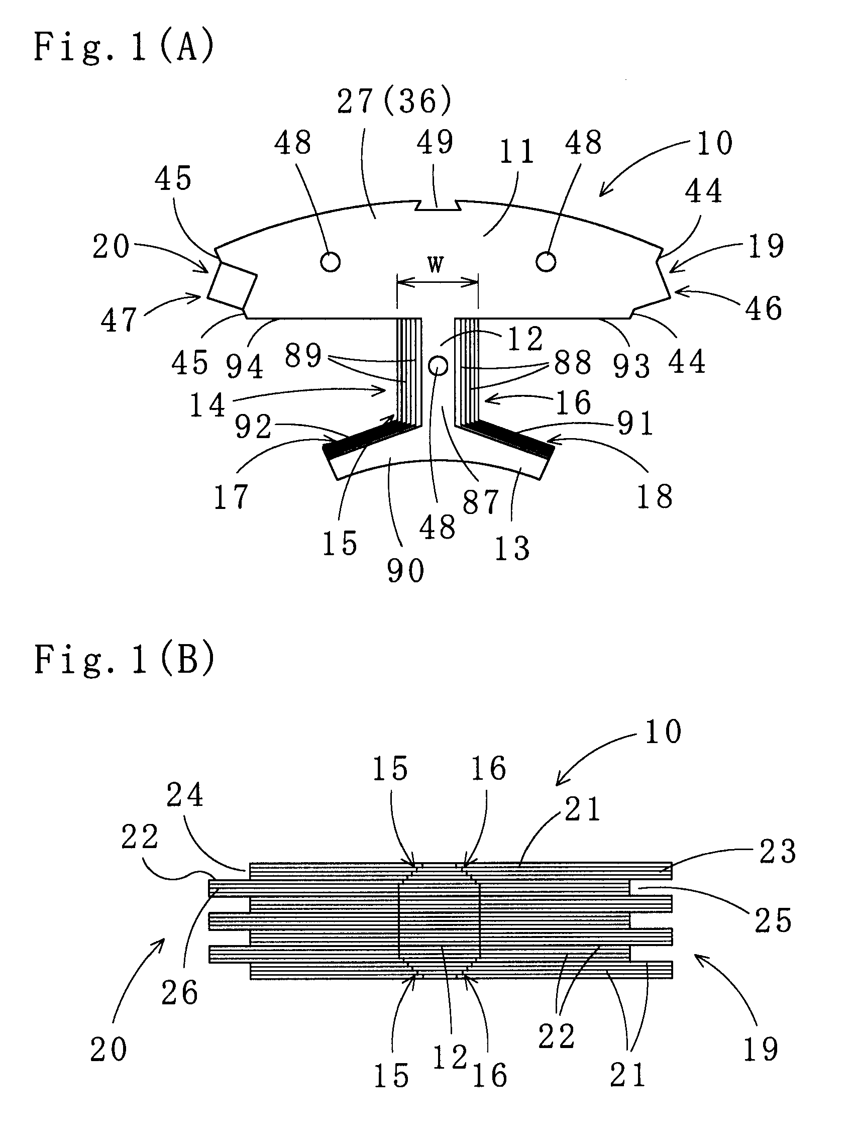
[0059]A laminated core (a laminated core for a rotor in particular) in accordance with the present invention is described. The laminated core is annular-shaped, and has a yoke and magnetic poles 14 located radially inward of the yoke at predetermined intervals. The laminated core is formed by assembling a plurality of laminated core segments 10 shown in FIG. 1(A). Each of the laminated core segments 10 includes a yoke-segment section 11 and the magnetic pole 14 integral with the middle of the radially inward side of the yoke-segment section 11. The yoke-segment section 11 has an arc-shaped radially outward side. The magnetic pole 14 has a magnetic pole shaft section 12 and a magnetic pole tooth section 13 connected thereto. The magnetic pole tooth section 13 has an arc-shaped radially inward end when viewed from the top thereof.

[0060]The magnetic pole tooth section 13 circumferentially diverges (extends in opposite directions) from one end of the magnetic pole shaft section 12 so as...

third embodiment

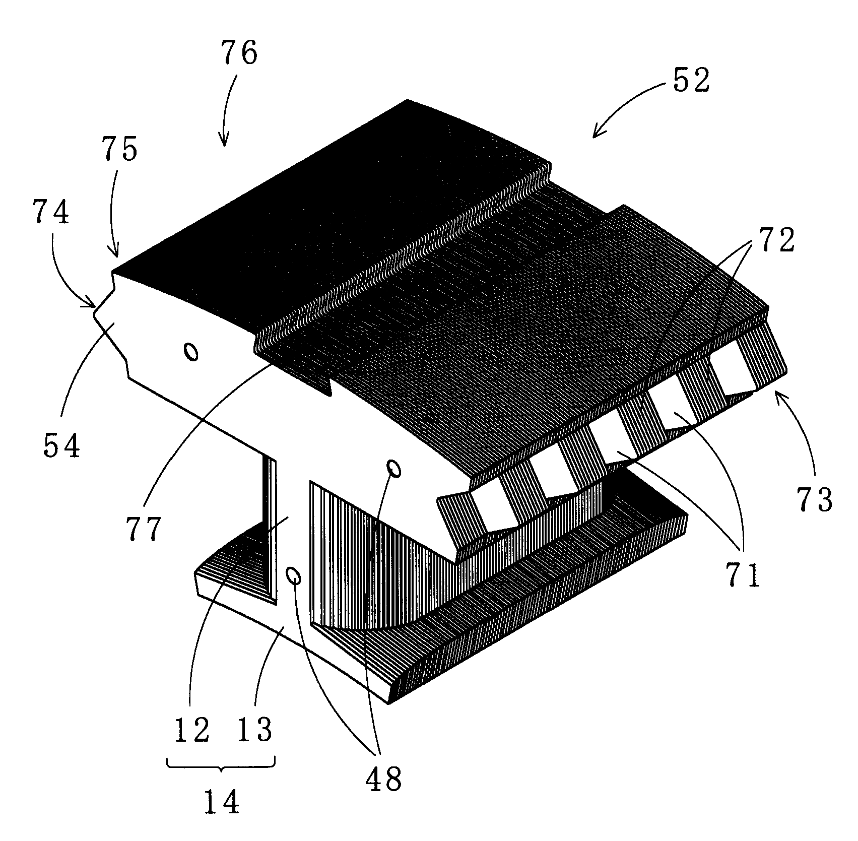
[0074]FIGS. 5(A), 5(B) show partial cross sections of the magnetic pole shaft section 12 of a laminated core segment 82 used to form a laminated core in accordance with the present invention. The laminated core segment 82 is a modification of the laminated core segment 10. As shown in FIG. 2 and FIG. 5, punching burrs directed to the center in the laminating direction are formed in the core segment sheets 21, 22 in the entirety of the laminated core segment 82 except a middle laminated portion 95, i.e., the core segment sheets 21, 22 at a lower laminated portion 83 and an upper laminated portion 84, and the core segment sheets 21, 22 at both ends of the middle laminated portion 95 and in contact with the portions 83, 84. These punching burrs are at both sides 88, 89 of a magnetic pole shaft piece 87, radially outward sides 91, 92 of a magnetic pole tooth piece 90, and radially inward sides 93, 94 of the yoke-segment pieces 27, 36 shown in FIG. 1.

[0075]Accordingly, there are no blank...

fourth embodiment

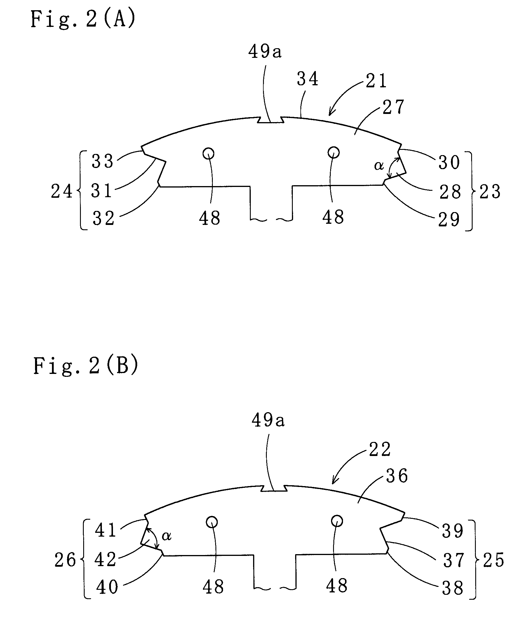
[0076]Next, referring to FIGS. 6(A), 6(B), a laminated core segment 100 used to form a laminated core in accordance with the present invention is described. The laminated core segment 100 is a modification of the laminated core segment 10, and has a magnetic pole shaft section 101 expanded in cross section at the middle thereof. In other words, among the magnetic pole shaft pieces 87 in the entirety of the magnetic pole shaft section 101 except the upper and the lower laminated portions 84, 83, i.e., among the magnetic pole shaft pieces 87 at the middle laminated portion 95 of the magnetic pole shaft section 101, the magnetic pole shaft piece 87 at the center in the lamination thickness direction has the largest width, which gradually decreases in the downward and upward directions of lamination. Additionally, the corners 15, 16 at the upper and the lower laminated portions 84, 83 are round in shape as in the case of the laminated core segment 10.

[0077]The widths of the magnetic pol...


PUM


Abstract

A laminated core formed by reliably and firmly connecting laminated core segments (10) in an annular form by first and second joining sections (19, 20) thereof, the first and second joining sections (19, 20) formed by alternately laminating sets of core segment sheets (21) and sets of core segment sheets (22), each set consisting of a predetermined number of sheets, the core segment sheets having brimmed concavities (24, 25) and brimmed convexities (23, 26) located at both ends of yoke-segment pieces (27, 36), wherein each laminated core segment (10) has round corners formed at both sides of a magnetic pole shaft section (12) and radially outward sides of a magnetic pole tooth section (13) at lower and upper laminated portions of the laminated core segment (10), thereby preventing damage to wires wound around the magnetic pole shaft section (12).

Description

TECHNICAL FIELD[0001]The present invention relates to a laminated core (especially a laminated core for a stator) produced by laminating and interlocking a predetermined number of core segment sheets for fabrication of laminated core segments each having a yoke-segment section and a magnetic pole and by connecting the laminated core segments in an annular shape at first and second joining sections located at both sides of each yoke-segment section. The present invention also relates to a method for manufacturing the laminated core. In particular, the present invention relates to a laminated core wherein wires fit magnetic pole shaft sections well, and thus wire insulation coatings or the wires themselves are free from damage, and to a method for manufacturing the same.BACKGROUND ART[0002]As disclosed in Japanese Unexamined Patent Application Publication No. 2005-341684 (to be referred to as Patent Document 1), forming a laminated core with an annular yoke by laminated core segments ...

Claims


Application Information

Patent Timeline
Patent Type & Authority Patents(United States)
IPC IPC(8): H02K1/00H02K1/06
CPCH02K1/148H02K15/022
Inventor MATSUO, HIDEKITOSU, NORIOTOMOZOE, TATSUMIIRIE, JUNICHI
Owner MITSUI HIGH TEC INC
Why Eureka
Try Eureka