
Sound reproduction in portable electronic equipment

a portable electronic equipment and sound reproduction technology, applied in the direction of substation equipment, transducer casings/cabinets/supports, electric transducers, etc., can solve the problems of low quality sound reproduction and risk of loud ringer levels in the receiver outl

Inactive Publication Date: 2010-02-23
SONY CORP
View PDF12 Cites 0 Cited by
  • Summary
  • Abstract
  • Description
  • Claims
  • Application Information

AI Technical Summary

Benefits of technology

This solution prevents loss in low frequency response and reduces the risk of loud ringer levels, ensuring high quality sound reproduction with shared back volume in portable electronic devices.

Problems solved by technology

However, if the receiver and the speaker share the same back volume there will be a number of problems.
One problem is that the receiver will act as a leak when the loudspeaker is active, with loss in the low frequencies as a result, resulting in lower quality sound reproduction.
Yet another problem is that there is a risk for loud ringer levels in the receiver outlet.

Method used


Image

  • Sound reproduction in portable electronic equipment
  • Sound reproduction in portable electronic equipment
  • Sound reproduction in portable electronic equipment

Examples


Embodiment Construction

[0027]Referring now to the drawings, a description will be given in detail of embodiments in accordance with the present invention.

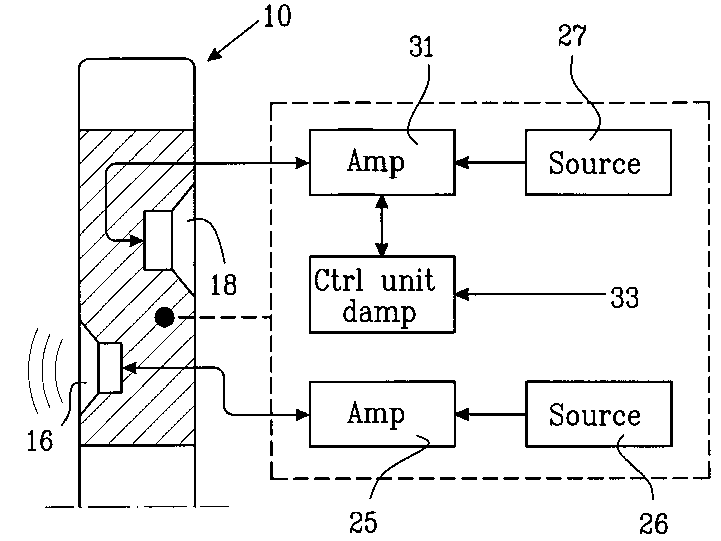
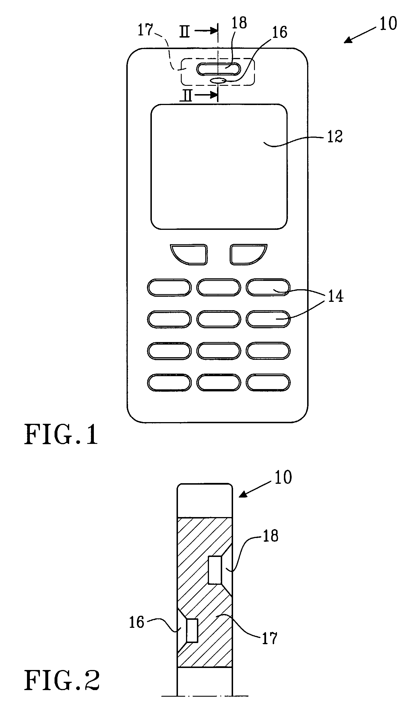
[0028]A portable electronic equipment 10 according to an embodiment of the invention is shown in FIGS. 1, 2 and 3. In a first preferred embodiment, the portable electronic equipment 10 is a cellular phone having an antenna (not shown), a display 12 and operating buttons 14. As shown in FIG. 2, a first signal-vibration transducer for implementing a speaker 16 provided with a back-volume 17 is located to the left of the cellular phone, and a second signal-vibration transducer for implementing a receiver 18 is located to the right nearby the first one sharing the same back-volume 17. Preferably, the first and the second signal-vibration transducers (speaker and receiver) are provided as separate transducers, which will be explained in more detail below.

[0029]According to the various embodiments the invention, including this first one, the speaker 16 and the...


PUM


Abstract

The present invention is directed towards a portable electronic equipment (10) comprising a speaker (16) and a receiver (18), wherein the receiver (18) is damped while the speaker (16) is active to provide good sound reproduction.

Description

TECHNICAL FIELD OF THE INVENTION[0001]The present invention relates to the field of portable electronic equipment, in particular to high quality sound reproduction in such a device.DESCRIPTION OF RELATED ART[0002]A conventional portable electronic equipment such as a cellular phone typically comprises elements such as a housing, a display, operation buttons, a speaker, and a receiver for outputting received sound and a microphone for converting voice from a user to a sound signal to be transmitted. The volume available, for instance, put restrictions on the back volume available for the speaker and the receiver. Therefore they may have to share the same back volume.[0003]Herein, the term “receiver” is referred to as an element that transduces electric signals into sound. Herein, a “speaker” is referred to an element typically employed to provide a ringer signal.[0004]However, if the receiver and the speaker share the same back volume there will be a number of problems. One problem i...

Claims


Application Information

Patent Timeline
Patent Type & Authority Patents(United States)
IPC IPC(8): H04R3/00H04M1/03H04M1/20H04M1/60
CPCH04M1/03H04M1/6016H04R3/002H04R3/12H04R2499/11
Inventor GUSTAVSSON, STEFAN
Owner SONY CORP
Learn More