
Digital audio data receiver without synchronized clock generator

a digital audio and clock generator technology, applied in the field of digital audio interfaces, can solve the problems of providing the sync-lock feature and communicating the house sync need to be don

Inactive Publication Date: 2010-02-23
CREATIVE TECH CORP
View PDF9 Cites 2 Cited by
  • Summary
  • Abstract
  • Description
  • Claims
  • Application Information

AI Technical Summary

Benefits of technology

[0009]The unique application of a type of sampling technique to digital audio data eliminates the need for a PLL, and allows recovery of the audio data with simple circuitry. No analog circuitry is required, and the device can be constructed purely digital (CMOS) circuits. The invention allows the system clock for the circuit to be generated by a typical crystal oscillator. This makes it easy to have a high quality (low phase noise) system clock. Another advantage is that multiple, independent data input streams can be received using a single system clock. There is no need for a “house sync”, since the circuit easily recovers the data using the system clock, without recovering the digital audio clock. This enables multiple independent data streams at widely-different clock rates to be received.

Problems solved by technology

A disadvantage to this approach is that the house sync needs to be communicated to all transmitting devices, and most consumer equipment such as CD-players, CD-ROMs, DAT players and Mini-disks do not provide the sync-lock feature this would require.

Method used


Image

  • Digital audio data receiver without synchronized clock generator
  • Digital audio data receiver without synchronized clock generator
  • Digital audio data receiver without synchronized clock generator

Examples


Embodiment Construction

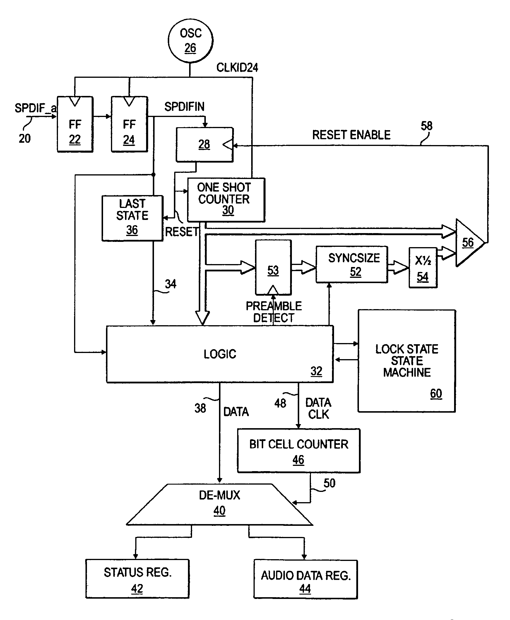
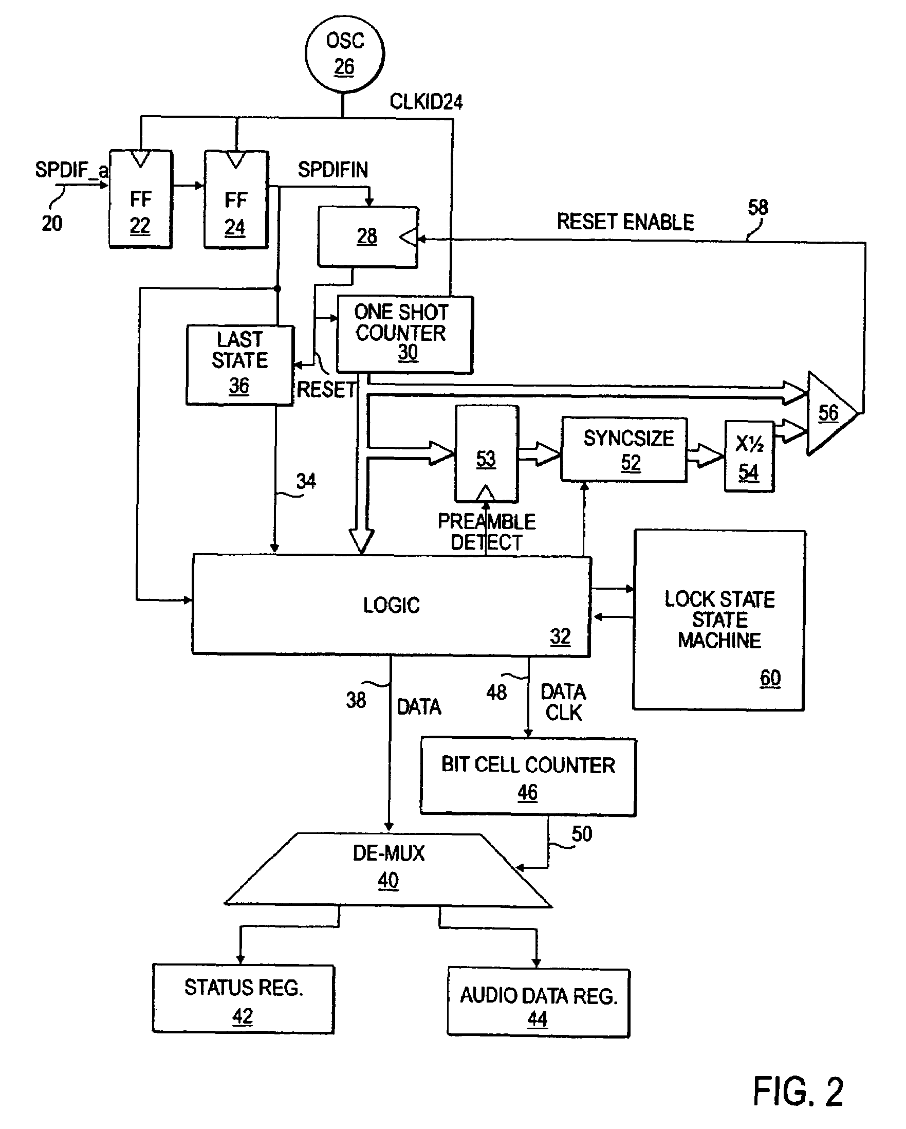
[0016]FIG. 2 is a block diagram illustrating the functions of the logic in one embodiment of the invention. The figure is designed for conceptual understanding, and is not an exact implementation of a preferred embodiment set forth in the VHDL code in the Appendix. FIG. 2 shows the SPDIF_a input signal on an input line 20. The signal passes through two flip flops 22 and 24 to produce an output signal SPDIFIN. The flip flops are clocked by an oscillator 26, referred to as clk1024. Oscillator 26 provides a clock which is preferably at least 4, and more preferably at least 8 or 16, times the rate of the audio data. In one embodiment, SPDIF data has an audio sampling rate between 11 kHz and 97 kHz, resulting in a bit cell rate of up to 3 mHz, giving transition rates of up to 6 mHz. Thus, a desirable minimum clock of 4 times the transition rate would be about 25 mHz. More preferably, a 50 or 100 mHz clock would be used.

[0017]The two flip flops 22 and 24 condition the input signal to prod...


PUM


Abstract

A method and apparatus for receiving digital audio data which does not require the recovery of a clock from the data. Instead, the digital audio data is sampled at a rate greater than a clock rate of the digital audio data. Appropriate transitions in the digital audio data are detected to allow reconstruction of digital values represented by the digital audio data.

Description

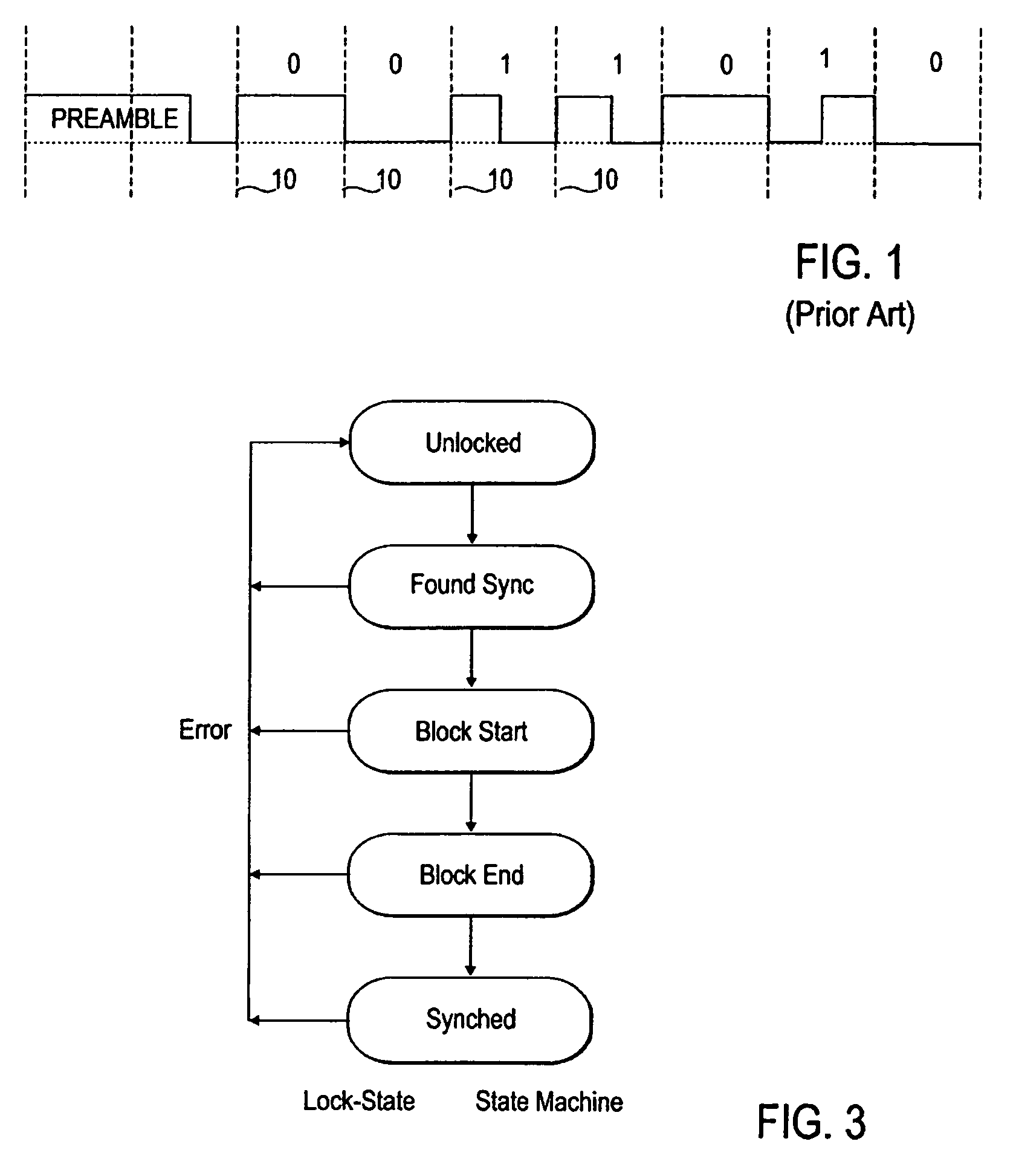
CROSS-REFERENCES TO RELATED APPLICATIONS[0001]Application claims priority of U.S. patent application Ser. No. 09 / 193,218, filed Nov. 16, 1998, titled “Digital Audio Data Receiver Without Synchronized Clock Generator”, now U.S. Pat. No. 6,772,021, the disclosure of which is incorporated by reference in its entirety.BACKGROUND OF THE INVENTION[0002]The present invention relates to digital audio interfaces, and in particular to receivers which can receiver S / PDIF and AES digital audio signals.[0003]S / PDIF is a digital audio interface standard commonly used in consumer digital audio equipment, including personal computers. AES is a digital audio interface which is prevalent in professional equipment. Both of these formats are a one direction serial interface which is Manchester encoded in order to provide an embedded clock so that a single data wire is sufficient for the interface.[0004]Manchester encoding encodes digital bits serially in the following manner. The data is sent in a numb...

Claims


Application Information

Patent Timeline
Patent Type & Authority Patents(United States)
IPC IPC(8): G06F17/00H04L7/02H04L7/033H04L25/06
CPCH04L7/0331H04L25/068
Inventor FULLER, J. SCOTT
Owner CREATIVE TECH CORP
Learn More