Carbide stem press fit into a steel body of a pick

a technology of carbide stems and picks, which is applied in the direction of cutting machines, cutting machines, earthwork drilling and mining, etc., can solve the problems of wear on attack tools

Active Publication Date: 2010-03-02
SCHLUMBERGER TECH CORP
View PDF71 Cites 73 Cited by
  • Summary
  • Abstract
  • Description
  • Claims
  • Application Information

AI Technical Summary

Problems solved by technology

Formation degradation, such as asphalt milling, mining, or excavating, may result in wear on attack tools.

Method used


Image

  • Carbide stem press fit into a steel body of a pick
  • Carbide stem press fit into a steel body of a pick
  • Carbide stem press fit into a steel body of a pick

Examples


Embodiment Construction

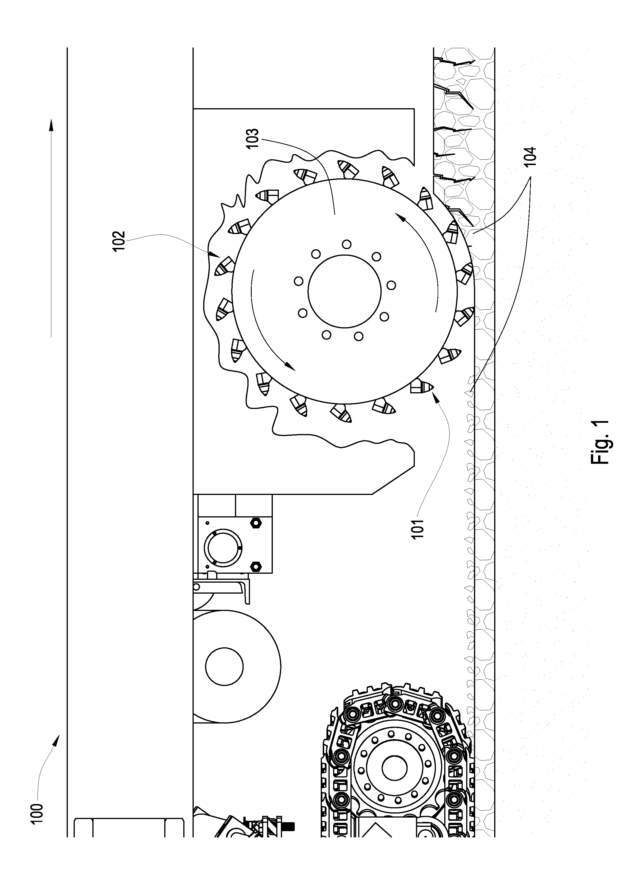
[0040]FIG. 1 is a cross-sectional diagram of an embodiment of a plurality of tools 101 attached to a rotating drum 103 connected to the underside of a pavement recycling machine 100. The recycling machine 100 may be a cold planer used to degrade man-made formations such as pavement 104 prior to the placement of a new layer of pavement. Tools 101 may be attached to the drum 103 bringing the tools 101 into engagement with the formation. A holder 102 or block is attached to the rotating drum 103, and the tool 101 is inserted into the holder 102. The holder 102 or block may hold the tool 101 at an angle offset from the direction of rotation, such that the tool 101 engages the pavement at a preferential angle.

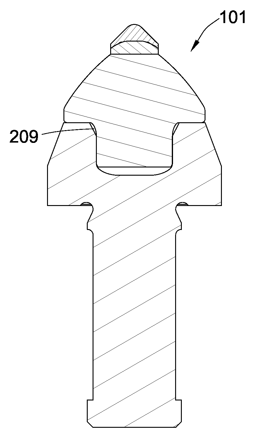
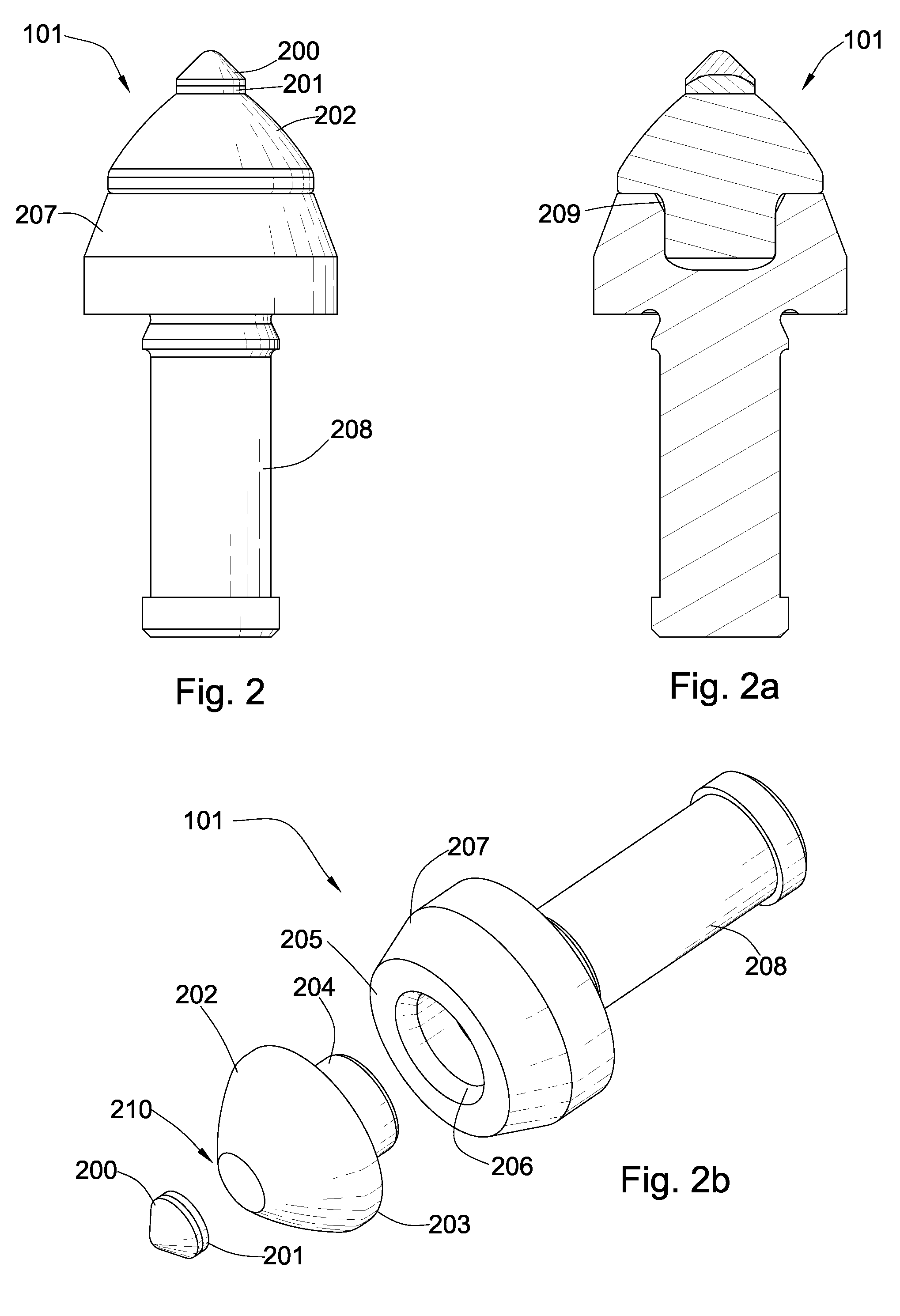
[0041]Now referring to FIG. 2 through 2a, the tool 101 comprises a super hard material200 bonded to a cemented metal carbide substrate 201 at a non-planar interface. The cemented metal carbide substrate 201 is bonded to a front end 210 of a cemented metal carbide segment 202. The ca...


PUM

PropertyMeasurementUnit
angleaaaaaaaaaa
diameteraaaaaaaaaa
radiusaaaaaaaaaa

Abstract

In one aspect of the present invention, a high impact resistant tool, having a super hard material is bonded to a cemented metal carbide substrate at a non-planar interface. The cemented metal carbide substrate is bonded to a front end of a cemented metal carbide segment. A stem is formed in the base end of the carbide segment opposite the front end and the carbide stem is press fitted into bore of a steel body.

Description

CROSS REFERENCE TO RELATED APPLICATIONS[0001]This application is a continuation-in-part of U.S. patent application Ser. No. 11 / 773,271 which was filed on Jul. 3, 2007. U.S. patent application Ser. No. 11 / 773,271 is a continuation-in-part of U.S. patent application Ser. No. 11 / 766,903 filed on Jun. 22, 2007. U.S. patent application Ser. No. 11 / 766,903 is a continuation of U.S. patent application Ser. No. 11 / 766,865 filed on Jun. 22, 2007. U.S. patent application Ser. No. 11 / 766,865 is a continuation-in-part of U.S. patent application Ser. No. 11 / 742,304 which was filed on Apr. 30, 2007 now U.S. Pat. No. 7,475,948. U.S. patent application Ser. No. 11 / 742,304 is a continuation of U.S. patent application Ser. No. 11 / 742,261 which was filed on Apr. 30, 2007 now U.S. Pat. No. 7,469,971. U.S. patent application Ser. No. 11 / 742,261 is a continuation-in-part of U.S. patent application Ser. No. 11 / 464,008 which was filed on Aug. 11, 2006 now U.S. Pat. No. 7,338,135. U.S. patent application Se...

Claims


Application Information

Patent Timeline
Patent Type & Authority Patents(United States)
IPC IPC(8): E21C35/18
CPCE21C35/183
Inventor HALL, DAVID R.BAILEY, JOHNCROCKETT, RONALD B.
Owner SCHLUMBERGER TECH CORP
Why Eureka
Try Eureka