Simple inclined-hole drilling jig

a drilling jig and inclined-hole technology, applied in the direction of drilling/boring measurement devices, metal working devices, manufacturing tools, etc., can solve the problems of inconvenient and tedious drilling, and not provide a good outlet for wood dust generated, so as to improve the drilling performance, the effect of quick adjustment of the axle spread of the hol

Inactive Publication Date: 2010-03-02
MICROSOFT CORP
View PDF18 Cites 20 Cited by
  • Summary
  • Abstract
  • Description
  • Claims
  • Application Information

AI Technical Summary

Benefits of technology

[0005]The primary object of the present invention is to provide an improved simple inclined-hole drilling jig, which can rapidly adjust the axle spread of holes to be drilled without marking and drilling each hole, and the dust generated in the process of drilling can be removed smoothly, thereby greatly enhancing the drilling performance.
[0006]The improved simple inclined-hole drilling jig comprises a jig body having a crossover plane able to press evenly against the wood workpiece at its bottom and a beveled end member disposed at the front end of its long shaft. The beveled end member is at least concavely configured with a guiding shaft hole, which extends downwardly from the beveled end member through the crossover plane. The upper end of guiding shaft hole is pivotally configured with a guide bushing for drill bit to pass through. The rear end and side surfaces of the long shaft of jig body are respectively formed with a reference face and sidewalls perpendicular to the crossover plane, characterized in which the sidewall is at least concavely disposed with a dust guide groove intercrossing the guiding shaft hole, and is pivotally disposed with a graduated extension board in a manner that allows axial displacement and positioning. The end of the extension board is bent to form a retaining end plane parallel to the reference face to extendingly adjust the axle spread of reference face, thereby greatly enhancing the operating performance of the simple drill jig.

Problems solved by technology

However the actual operation requires precision marking and drilling, and the use of jig for oblique drilling, which is tedious and inconvenient.
In addition, the guiding shaft hole 4 is concealed inside the drill jig which does not provide a good outlet for wood dust generated in the drilling.

Method used


Image

  • Simple inclined-hole drilling jig
  • Simple inclined-hole drilling jig
  • Simple inclined-hole drilling jig

Examples


Embodiment Construction

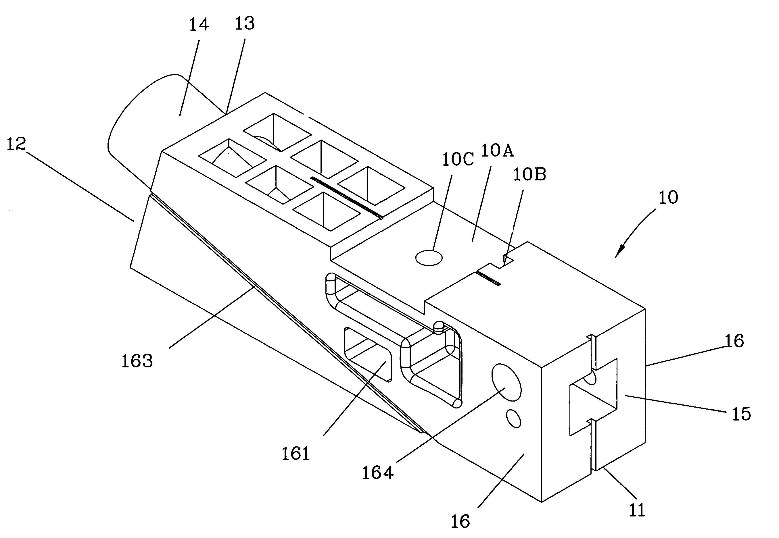
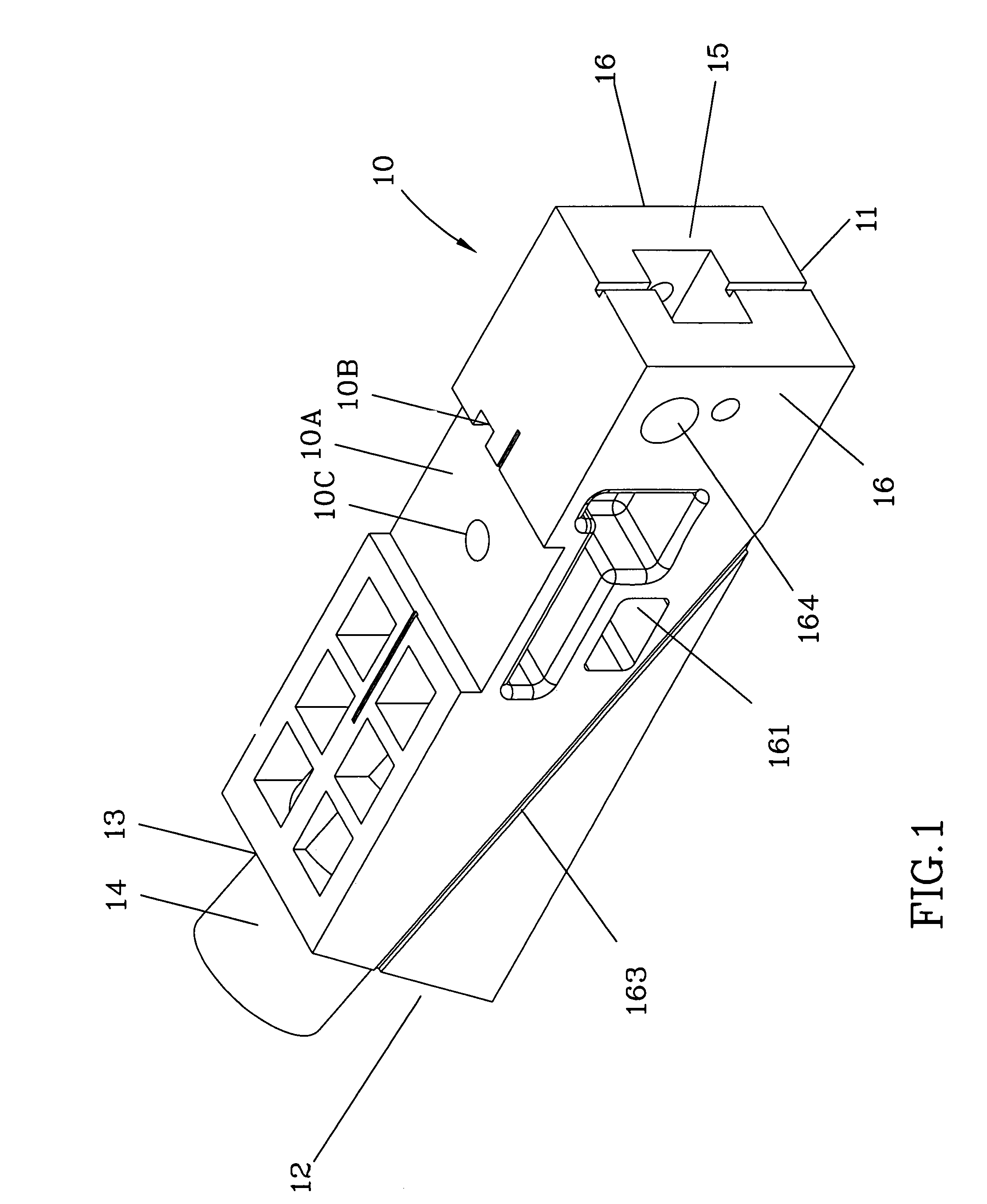
[0016]Referring to FIG. 1 and FIG. 4, the improved simple inclined-hole drilling jig of the invention comprises a jig body with a long shaft extension 10, having a crossover plane 11 able to evenly press against the wood workpiece at its bottom and a beveled end member 12 disposed at the front end of its long shaft. The beveled end member 12 is at least concavely configured with a guiding shaft hole 13, which, as shown in FIG. 4, extends downwardly from the beveled end member 13 through the crossover plane 11. The upper end of guiding shaft hole 13 is pivotally configured with a guide bushing 14 for drill bit 20 to pass through. The rear end and side surfaces of the long shaft of jig body 10 are respectively formed with a reference face 15 and two sidewalls 16 perpendicular to the crossover plane.

[0017]The sidewall 16 is concavely disposed with a dust guide groove 161, which, as shown in FIG. 4, has rectangular section axially perpendicular to the guiding shaft hole 13 and situated ...


PUM

PropertyMeasurementUnit
displacementaaaaaaaaaa
areaaaaaaaaaaa
thicknessaaaaaaaaaa

Abstract

A simple inclined-hole drilling jig comprises a jig body having a crossover plane at the bottom to evenly press against the wood workpiece, and a beveled end member at the front concavely disposed with a guiding shaft hole extending downwardly from the beveled end member through the crossover plane. The upper end of guiding shaft hole is configured with a guide bushing for drill bit to pass through. The rear end and side surfaces of jig body are respectively formed with a reference face and sidewalls perpendicular to the crossover plane; the sidewall is at least concavely disposed with a dust guide groove intercrossing the guiding shaft hole and slidingly disposed with a graduated extension board to allow axial displacement and positioning. The end of the extension board is bent to form a retaining end plane parallel to the reference face to extendingly adjust the axle spread of reference face.

Description

BACKGROUND OF THE INVENTION[0001]1. Field of the Invention[0002]The present invention relates to a woodwork drilling jig, more particularly, a simple inclined-hole drilling jig structure.[0003]2. Description of the Related Art[0004]Inclined-hole drilling of woodwork is primarily used in the corner joint of woodpieces. Conventional “simple inclined-hole drilling jig” (as shown in FIG. 8) designed for this kind of angle drilling comprises mainly of a jig body 1 having a crossover plane 2 able to evenly press against the wood workpiece at the bottom, and a beveled end member 3 at the front. The beveled end member 3 is concavely disposed with a guiding shaft hole 4, which extends downwardly from the beveled end member 3 through the crossover plane 2. The upper end of guiding shaft hole 4 is pivotally configured with a guide bushing 5 for drill bit to pass through. When the crossover plane 2 aligns the end of workpiece, the beveled angle design of the beveled end member 3 allows the cent...

Claims


Application Information

Patent Timeline
Patent Type & Authority Patents(United States)
IPC IPC(8): B23B47/28
CPCB23B47/287B23B2247/10B23B2247/12Y10T408/56245B23B2260/088Y10T408/567B23B2260/004
Inventor CHIANG, VANCE
Owner MICROSOFT CORP
Why Eureka
Try Eureka