Pump with conveying chamber formed in outer rotor surface

a technology of conveying chamber and pump, which is applied in the direction of rotary/oscillating piston pump components, machines/engines, liquid fuel engines, etc., can solve the problem of preventing direct communication between the outlet and the inl

Active Publication Date: 2010-03-09
QUANTEX ARC LTD
View PDF19 Cites 67 Cited by
  • Summary
  • Abstract
  • Description
  • Claims
  • Application Information

AI Technical Summary

Benefits of technology

[0006]According to the invention, there is provided pump comprising a housing, a rotor path defined within the housing, an inlet formed in the housing at a first position on said rotor path, an outlet formed in the housing at a second position on said rotor path spaced from said first position, a rotor rotatable in said housing, at least two apices formed on the rotor and sealing against said rotor path, at least one surface formed on said rotor between said at least two apices, a chamber formed by said at least one rotor surface between the at least two apices and the housing and travelling around said rotor path on rotation of the rotor to convey fluid around the housing, a resilient seal carried by the housing located on said rotor path and extending between the outlet and the inlet in the direction of rotation of said rotor that each apex seals with, and resiliently deforms, the seal, as each apex passes between the outlet and the inlet to prevent fluid flow from said outlet to said inlet past the seal.

Problems solved by technology

In such pumps, a problem is the prevention of direct communication between the outlet and inlet.

Method used


Image

  • Pump with conveying chamber formed in outer rotor surface
  • Pump with conveying chamber formed in outer rotor surface
  • Pump with conveying chamber formed in outer rotor surface

Examples


Embodiment Construction

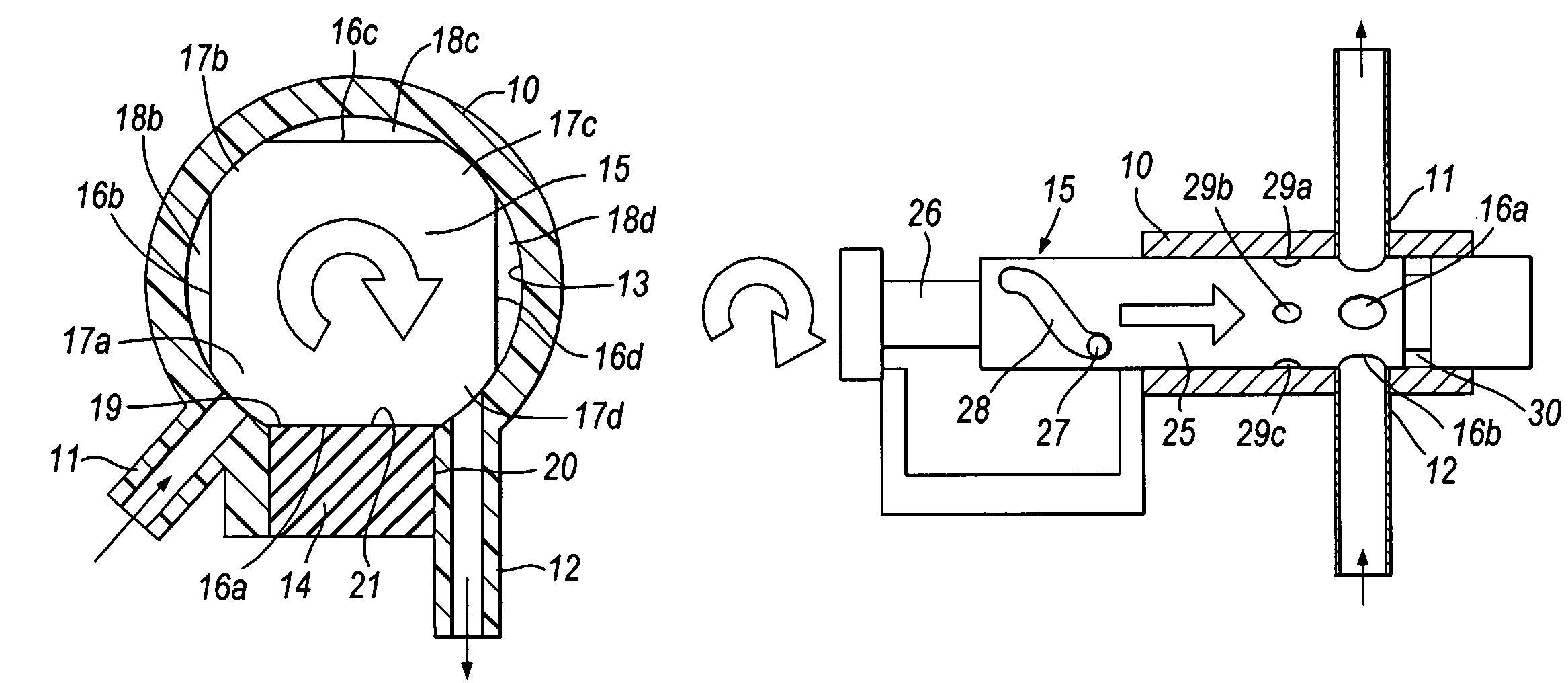
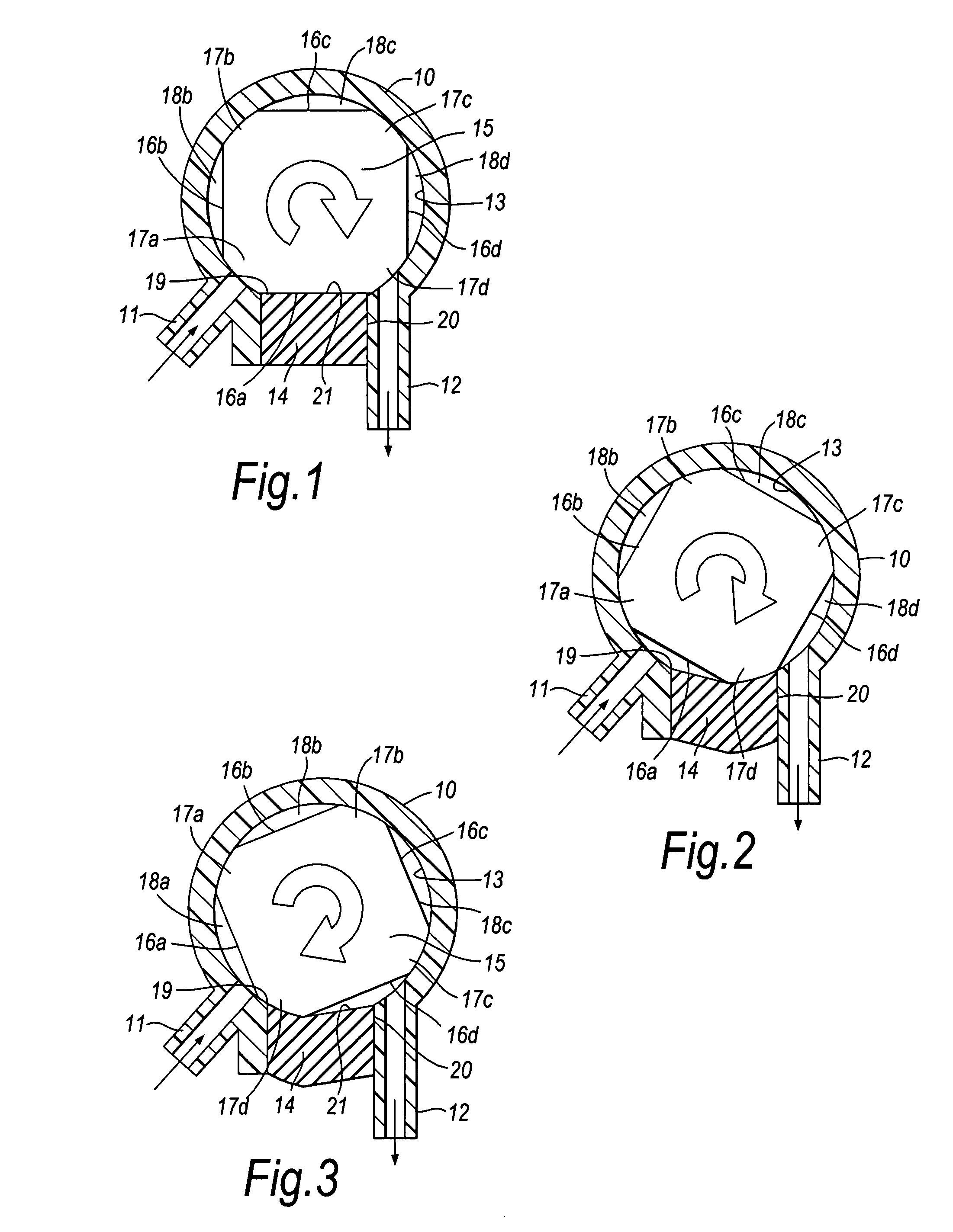
[0023]Referring first to FIGS. 1 to 3, the pump is formed by a housing indicated generally at 10 which may be formed by a plastics moulding of, for example, polyethylene or polypropylene. The housing 10 is formed with an inlet 11 for connection to a source of fluid and an outlet 12 for pumped fluid. The interior of the housing 10 is cylindrical. The portion of the interior of the housing 10 between the outlet 12 and the inlet 11, again in clockwise direction as viewed in FIGS. 1 to 3, carries a seal 14 that will be described in more detail below.

[0024]The housing 10 contains a rotor 15. The rotor 15 may be formed of stainless steel or as a precision injection moulded plastics part formed from a resin such as acetal. As seen in the Figures, the rotor 15 is generally of circular cross-section and includes four recessed surfaces 16a, 16b, 16c and 16d of equal length equiangularly spaced around the rotor and interconnected by apices 17a, 17b, 17c and 17d formed by unrelieved portions of...


PUM


Abstract

A pump is formed by a housing (10) having an inlet (11) for connection to a source of fluid and an outlet (12) for pumped fluid. A rotor (15) is rotatable within the housing and the inlet (11) and the outlet (12) are spaced apart around the path of the rotor (15) in the housing. The rotor (15) has surfaces (16a, 16b, 16c, 16d) that form, with the housing (10), closed chambers (18a, 18b, 18c, 18d) which travel around the housing (10) to convey fluid from the inlet (11) to the outlet (12). The housing (10) carries a seal (14) that is located between the inlet (11) and the outlet (12) in the direction of travel of the rotor (15). The seal (14) co-operates with the rotor surfaces (16a, 16b, 16c, 16d) as the surfaces (16a, 16b, 16c, 16d) pass between the outlet (12) and the inlet (11) to prevent the formation of a chamber during said passage and so prevent fluid flow from the outlet (12) to the inlet (11). Such a pump is easily and cheaply produced and is particularly useful in medical applications.

Description

BACKGROUND TO THE INVENTION[0001]1. Field of the Invention[0002]The invention relates to pumps.[0003]2. Background to the Invention[0004]A known form of pump comprises a housing with an inlet for connection to a source of fluid and an outlet for pumped fluid with the inlet and the outlet being spaced apart around a path of a rotor within the housing. The rotor includes at least one surface forming, with the housing, a closed chamber travelling around the housing to convey fluid around the housing.[0005]In such pumps, a problem is the prevention of direct communication between the outlet and inlet. In JP-A-60240890, a flexible film is fixed to a partition wall between the outlet and the inlet and engages partitioning pieces on the rotor. In GB-A-482750, the rotor carries sections that seal against an arcuate surface of the housing. In U.S. Pat. No. 3,282,496 slidable elements are forced by pressure against the chamber-forming surfaces of the rotor. In JP-A-60111078, the rotor carries...

Claims


Application Information

Patent Timeline
Patent Type & Authority Patents(United States)
IPC IPC(8): F01C19/02F01C20/20F04C5/00F04C11/00
CPCA61M5/14232A61M5/14236B67D1/10F04C15/0015F04C5/00F04C11/001F04C13/00F04C14/26F04C2/3566F04C2/22
Inventor HAYES-PANKHURST, RICHARD P.LACY, GRAHAM K.NIGHTINGALE, CHRISTOPHER E.
Owner QUANTEX ARC LTD
Why Eureka
Try Eureka