Steadying camera support platform

a technology of supporting platform and camera, which is applied in the field of camera mounts, can solve the problems of unsuitable for the use of the smaller, light-weight video cams available today, large, bulky and too expensive for the average video buff, and achieve the effect of reducing the expens

Inactive Publication Date: 2010-03-23
MIJAILOVIC VLADAN
View PDF23 Cites 17 Cited by
  • Summary
  • Abstract
  • Description
  • Claims
  • Application Information

AI Technical Summary

Benefits of technology

[0007]The adjustable leveling means can take the form of an air cylinder connected between said parallelogram linkage and said second vertical member and a secondary reservoir to provide cushioning against jerking movement. Alternatively, the parallelogram linkage can be mounted on a support block with the second lower bar being extended such that an adjustable spring can engage the portion which extends beyond its pivot point to cantilever the hands-free unit and its cargo.
[0008]Another aspect of the present invention is a dual platform mounting system for supporting multiple cameras to enable a photographer to simultaneously obtain multiple shots in different directions. When editing the film, the two views can be joined together in the same frame or spliced seriatim to show the different views, for example, in opposite directions. This configuration includes a first platform to which a first camera is secured; a support shaft attached to a bottom surface of said platform; a balance plate mounted on a bottom portion of said support shaft to help counterbalance a weight of the first camera, said balance plate mounting a second camera; means attachable to said support shaft by which said platform support and its cargo is suspended; whereby two cameras may simultaneously video tape in different directions to provide a film editor with differently directed shots taken during a single take.
[0009]While the simplicity and, hence, the lower expense associated with the current platform support will make the device of the present invention attractive to the amateur photographer, the versatility and practical features of this device will make it a favorite with the professional, as well.

Problems solved by technology

These devices are, typically, large, bulky and too expensive for use by the average video buff and, many of these devices are unsuitable for use by the smaller, light-weight video cams available today.

Method used


Image

  • Steadying camera support platform
  • Steadying camera support platform
  • Steadying camera support platform

Examples


Embodiment Construction

)

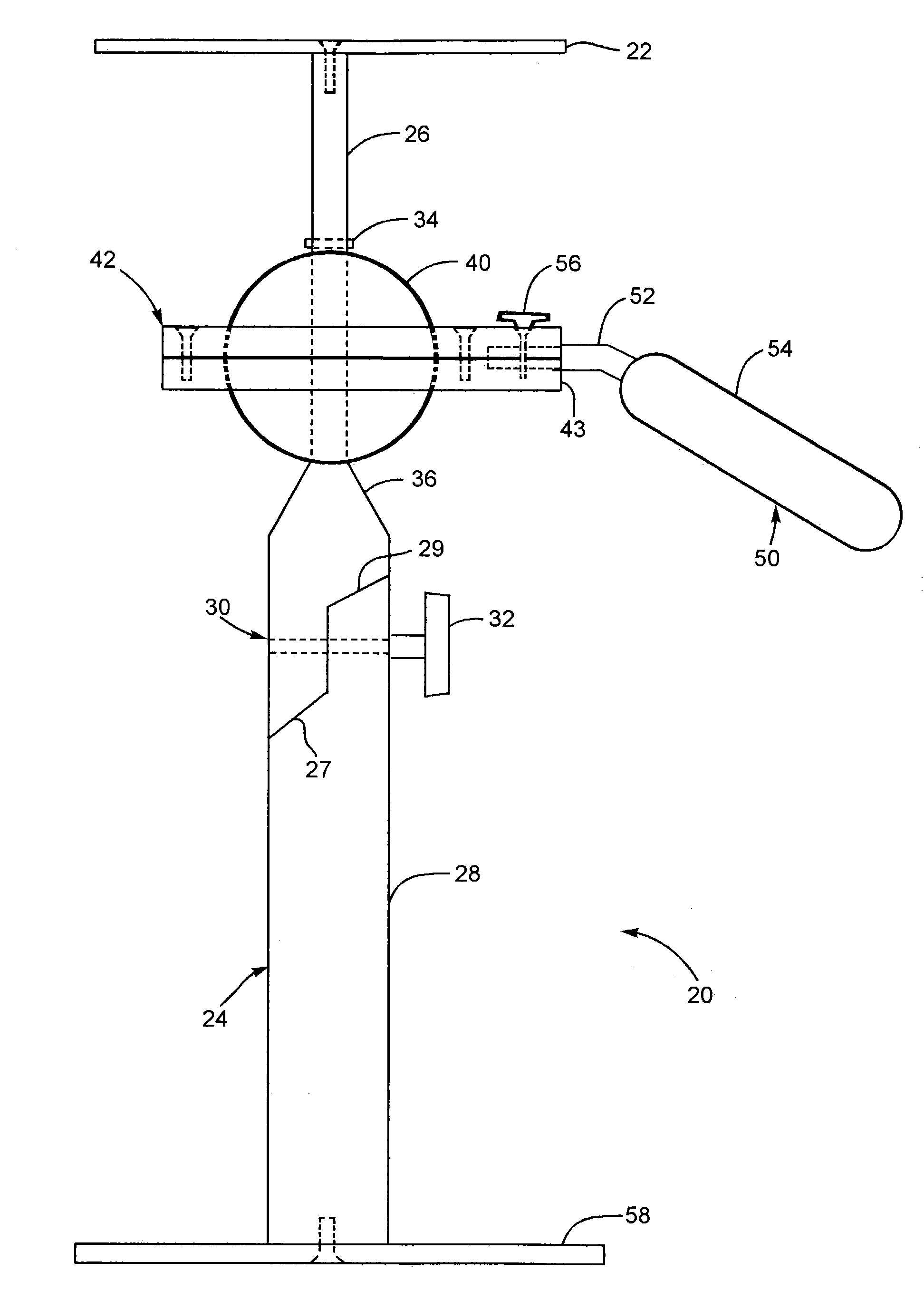
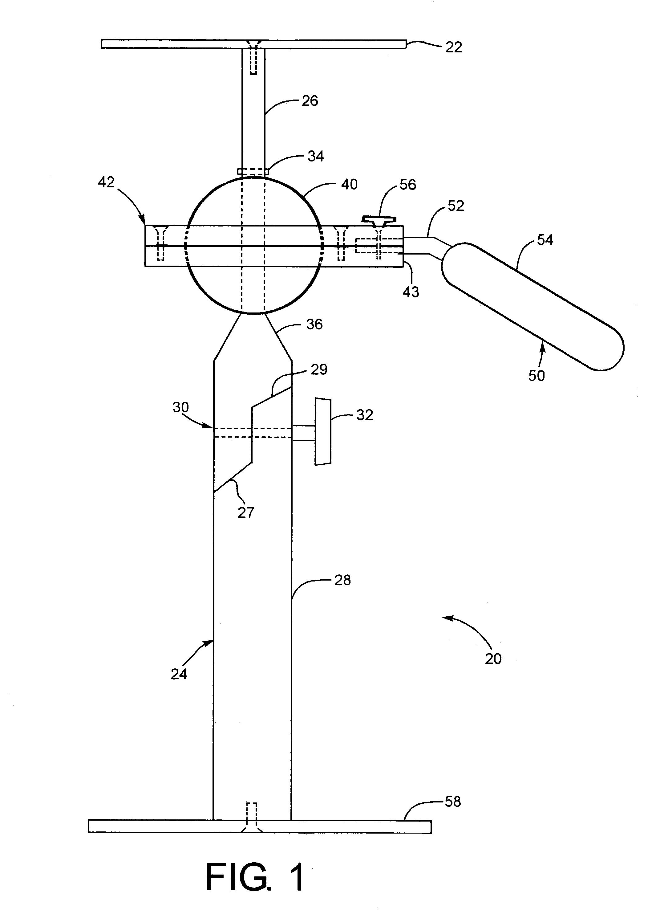
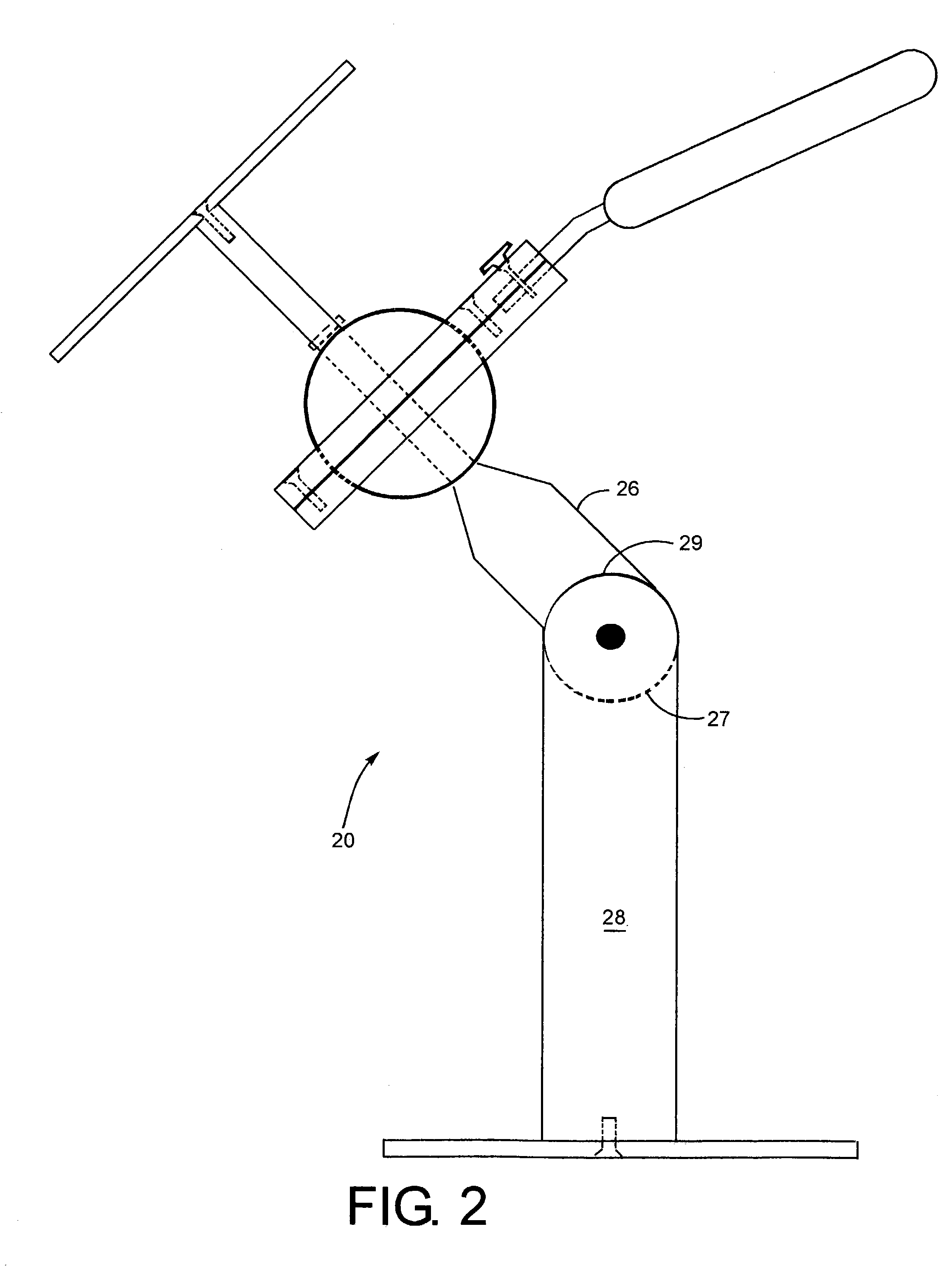
[0024]A first embodiment of the platform support of the present invention is depicted in FIGS. 1-3 generally at 20. The platform support 20 includes support plate 22 with support shaft 24 attached to the bottom of support plate 22. Support shaft 24 preferably has a first upper piece 26 and a second lower piece 28 joined by pivot joint 30. Lower end 27 of upper piece and upper end 29 of lower piece 28 are radiused to permit pivoting of at least ±60° from vertical (see FIG. 2). Loosening and re-tightening adjustment screw 32 will permit the user to obtain either an upwardly or downwardly peering camera angle of between 0 and 60°.

[0025]Mounted on the upper portion 26 of support shaft 24 is a spherical ball 40 which has an axial hole 41 there through of a diameter sufficient to accommodate the upper portion 26. A cotter pin 34, or the like, holds the ball 40 against upward vertical movement while the shoulder 36 formed atop lower piece 28 of the support shaft 24 restricts its downward ...


PUM


Abstract

A support platform for a video camera allows cushioning of jostling attendant to walking motion so that the video quality is unaffected by the photographer's movements. A sphere of TEFLON polymer floats in a socket plate permitting hand movements about the roll and pitch axes of ±60° and ±360° about the yaw axis without jarring the camera. A second embodiment affords the ability to mount an additional camera to provide shots in a plurality of directions on a single take. Yet another feature of the invention is a hands-free support arm usable with the support platform.

Description

BACKGROUND AND SUMMARY OF THE INVENTION[0001]The present invention is directed to the field of camera mounts. More particularly, the present invention comprises a camera mount for hand-held video recorders which can hold a camera steady if the support platform is maintained within ±60° about the x-axis and the z-axis while permitting complete unimpeded rotation about the y-axis.[0002]A number of devices, such as Steadicam® stabilizing device, have been developed for use by professional cameramen. These devices are, typically, large, bulky and too expensive for use by the average video buff and, many of these devices are unsuitable for use by the smaller, light-weight video cams available today.[0003]The steadying camera support platform of the present invention provides a much simpler, effective device for use with the camcorders currently being used while providing a great deal of flexibility for both mounting the camera and obtaining a variety of shots for the user. In addition, t...

Claims


Application Information

Patent Timeline
Patent Type & Authority Patents(United States)
IPC IPC(8): F16M11/14
CPCF16M11/04F16M11/14F16M11/2021F16M11/2092F16M11/24F16M13/00F16M13/04F16M2200/044F16M2200/063
Inventor MIJAILOVIC, VLADAN
Owner MIJAILOVIC VLADAN
Why Eureka
Try Eureka