
Electrical connector with improved contacts and transition module

a technology of transition module and electric connector, which is applied in the direction of coupling device connection, coupling protective earth/shielding arrangement, electric discharge lamps, etc., can solve the problems of limited use of express cards, insufficient usb transmission rate, and insufficient use of non-usb protocols. achieve the effect of facilitating manufacture and assembly of contacts

Active Publication Date: 2010-03-23
HON HAI PRECISION IND CO LTD
View PDF17 Cites 18 Cited by
  • Summary
  • Abstract
  • Description
  • Claims
  • Application Information

AI Technical Summary

Benefits of technology

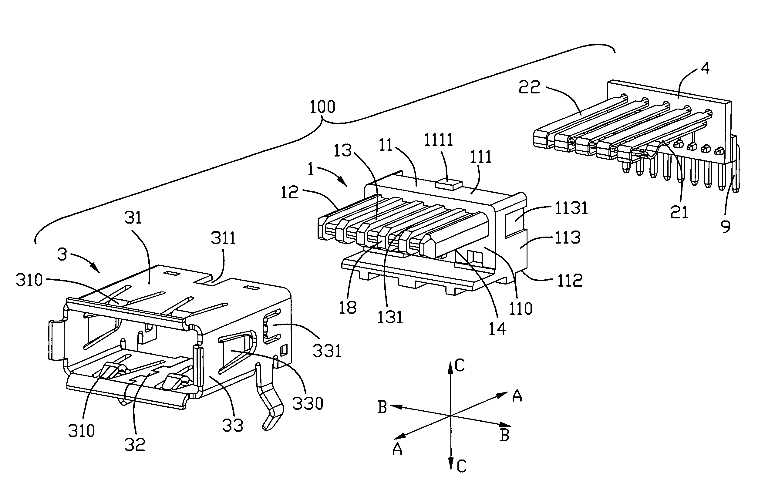
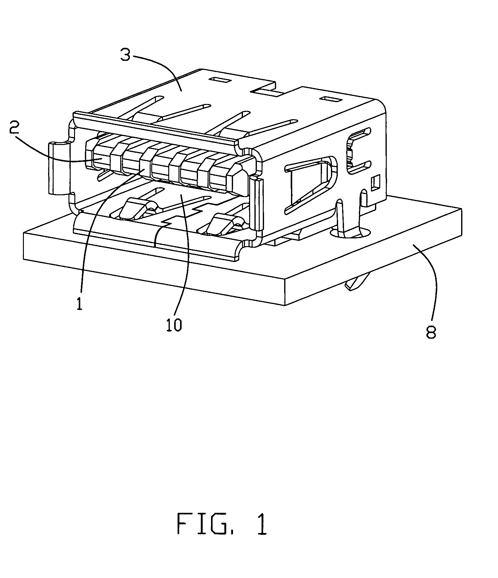
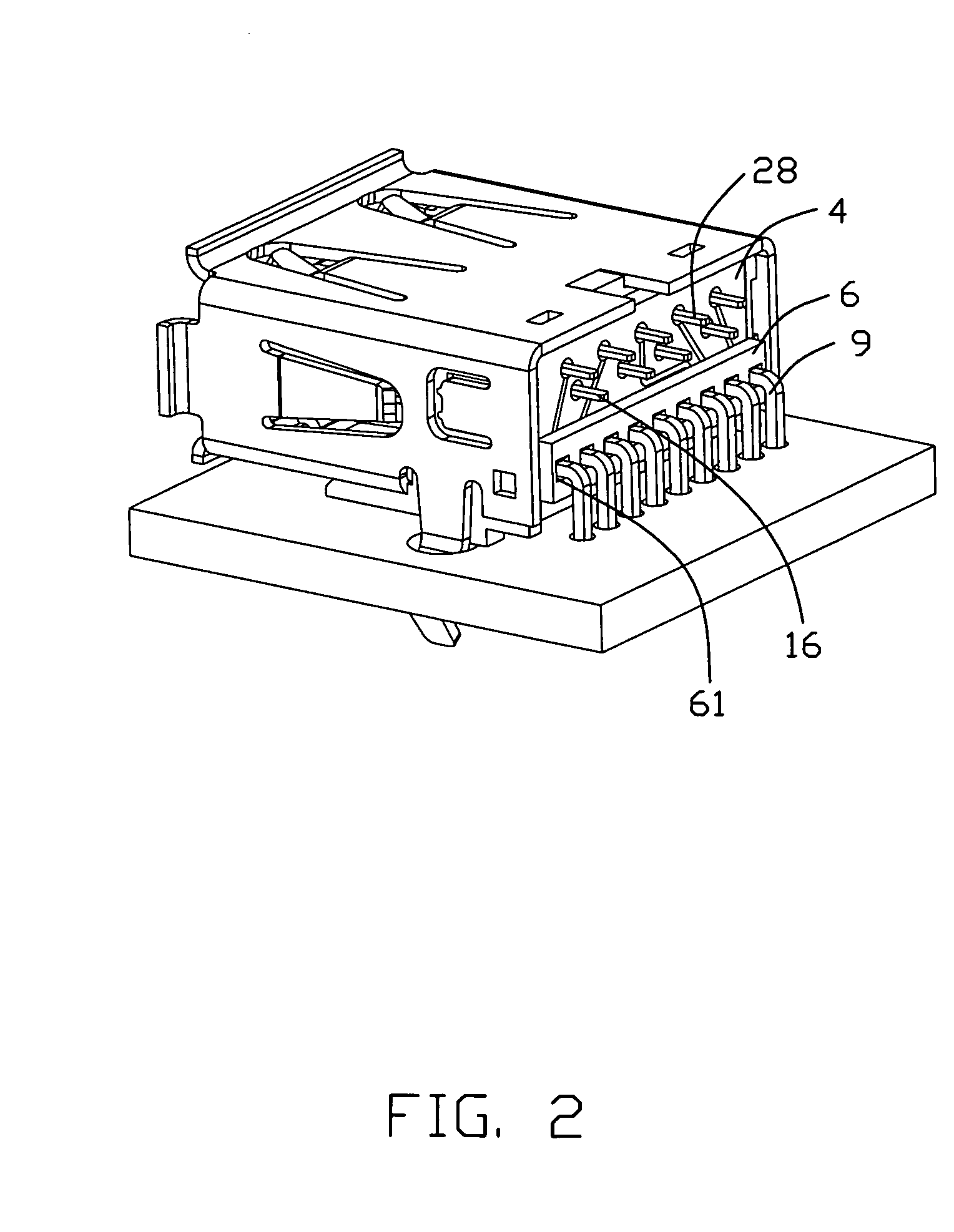
The present invention is related to an electrical connector for transmitting high-speed signals. The connector includes an insulative housing with a base and a tongue portion, and a transition module for connecting the contacts to a mother PCB. The contacts include conductive contacts and differential contacts for transferring high-speed signals. The first and second contact portions are located at the same side of the tongue portion and arranged in two parallel rows along the front-to-rear direction. The transition module is mechanically and electrically connected with the first and second tail portions. The technical effect of this invention is to provide a reliable and efficient connection for high-speed signals transfer. The transition module simplifies the manufacture and assembly of contacts.

Problems solved by technology

However, under a circumstance transmitting an audio or video file, which is always up to hundreds MB, even to 1 or 2 GB, currently transmission rate of USB is not sufficient.
However, these non-USB protocols are not used as broadly as USB protocols.
For example, while the PCI Express is useful for its higher possible data rates, a 26-pin connectors and wider card-like form factor limit the use of Express Cards.

Method used


Image

  • Electrical connector with improved contacts and transition module
  • Electrical connector with improved contacts and transition module
  • Electrical connector with improved contacts and transition module

Examples


Embodiment Construction

[0028]In the following description, numerous specific details are set forth to provide a thorough understanding of the present invention. However, it will be obvious to those skilled in the art that the present invention may be practiced without such specific details. In other instances, well-known circuits have been shown in block diagram form in order not to obscure the present invention in unnecessary detail. For the most part, details concerning timing considerations and the like have been omitted inasmuch as such details are not necessary to obtain a complete understanding of the present invention and are within the skills of persons of ordinary skill in the relevant art.

[0029]Reference will be made to the drawing figures to describe the present invention in detail, wherein depicted elements are not necessarily shown to scale and wherein like or similar elements are designated by same or similar reference numeral through the several views and same or similar terminology.

[0030]W...


PUM


Abstract

An electrical connector mounted on a mother PCB includes an insulative tongue portion and a number of contacts held in the insulative tongue portion. The contacts have four conductive contacts and at least one pair of differential contacts for transferring high speed signals. The conductive contacts are adapted for USB 2.0 protocol. The electrical connector further includes a transition module with one end connected to the contacts and the other end to be soldered to the mother PCB.

Description

BACKGROUND OF THE INVENTION[0001]1. Field of the Invention[0002]The present invention relates to electrical connectors, more particularly to electrical connectors with additional differential contact pair for transmitting high speed signals and with improved transition module.[0003]2. Description of Related Art[0004]Personal computers (PC) are used in a variety of ways for providing input and output. Universal Serial Bus (USB) is a serial bus standard to the PC architecture with a focus on computer telephony interface, consumer and productivity applications. The design of USB is standardized by the USB Implementers Forum (USB-IF), an industry standard body incorporating leading companies from the computer and electronic industries. USB can connect peripherals such as mouse devices, keyboards, PDAs, gamepads and joysticks, scanners, digital cameras, printers, external storage, networking components, etc. For many devices such as scanners and digital cameras, USB has become the standa...

Claims


Application Information

Patent Timeline
Patent Type & Authority Patents(United States)
IPC IPC(8): H01R24/00H01R13/6461H01R13/648
CPCH01R13/6658
Inventor ZHENG, QI-SHENGHE, JIA-YONG
Owner HON HAI PRECISION IND CO LTD
Learn More