Eureka AIR delivers breakthrough ideas for toughest innovation challenges, trusted by R&D personnel around the world.

Multiband antenna arrangement

a multi-band antenna and antenna technology, applied in the field of radio antennas, can solve the problems of increasing complexity, affecting the performance of the antenna, and affecting the performance of the antenna, and achieve the effects of enabling antenna diversity (and mimo) and simple rf front end solutions, low envelope correlation, and good diversity performan

Inactive Publication Date: 2010-03-23
RPX CORP
View PDF10 Cites 40 Cited by
  • Summary
  • Abstract
  • Description
  • Claims
  • Application Information

AI Technical Summary

Benefits of technology

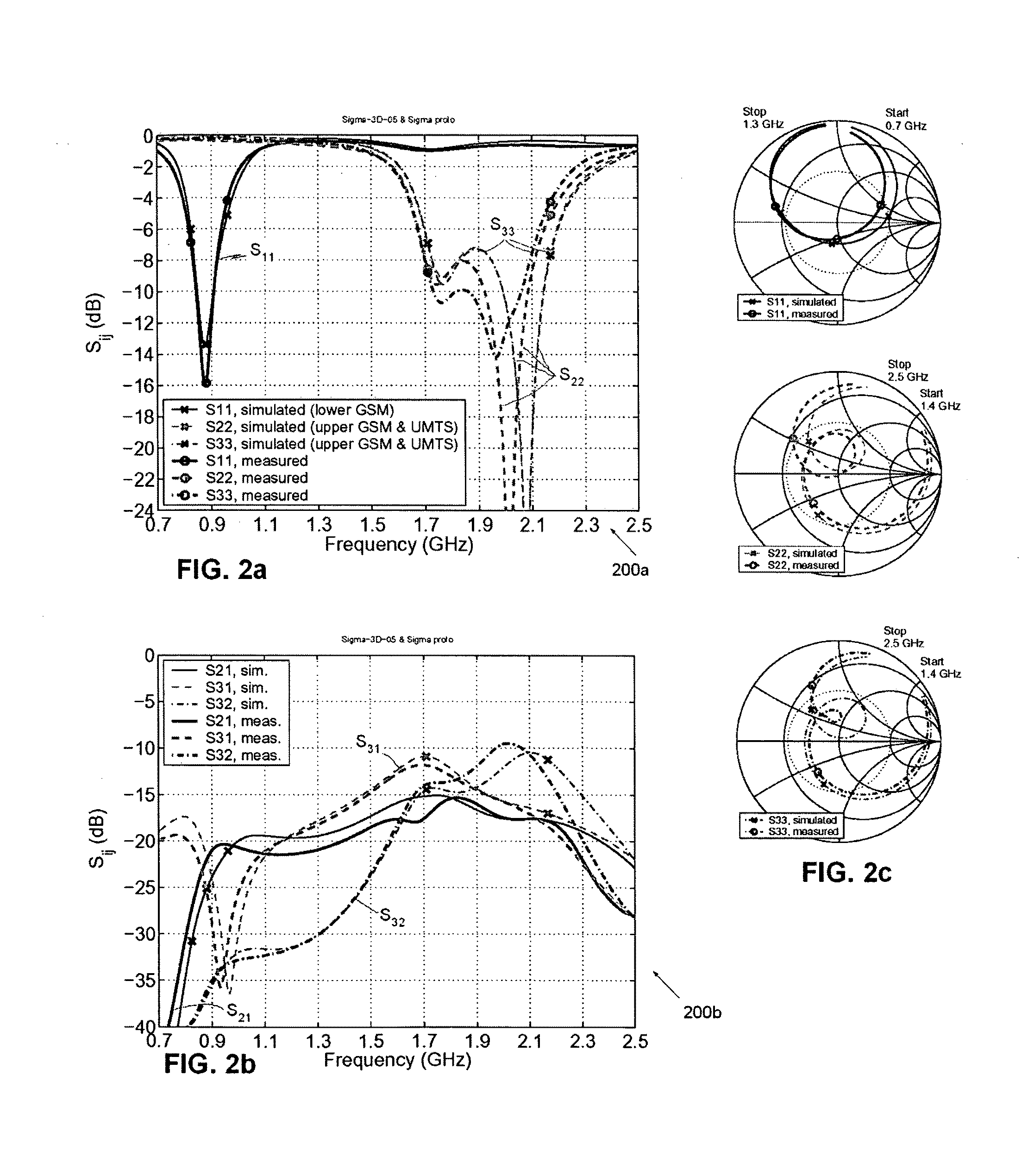
[0014]The object of the invention is to provide a compact internal multiband mobile terminal antenna arrangement operating efficiently at all the commonly used cellular communication system bands and further enabling antenna diversity (and MIMO) and simple RF front end solutions. An additional object of the invention is that the compact internal multiband mobile terminal antenna arrangement has a sufficiently low envelope correlation (say ρe<0.7) between antenna signals for good diversity performance and sufficiently large isolation of about 10 dB or more.

Problems solved by technology

The price for improved performance is, however, increased complexity.
However, some problems relate also to sizes of antennas.
One of the main problems of small antennas is small operation bandwidth.
However, in small portable radio equipment neither one of the mentioned methods is desirable.
However, these methods typically increase the complexity of the antenna.
To design compact and efficient internal handset antennas that operate e.g. at four GSM bands (GSM850 / 900 / 1800 / 1900) and the UMTS band is very challenging.
The problem becomes even more difficult, if multiple antennas operating at a given frequency band, such as diversity antennas, have to be included in a mobile terminal.
If total antenna size cannot be increased when a new antenna or operation band is added, the sizes of the existing antennas must then be decreased, which leads without exception to degradation of the performances of the existing antennas.
Further problems arise when two antennas operating at the same frequency range are placed close to each other because they tend to couple to each other.
In diversity and MIMO (Multiple Input Multiple Output) applications, mutual coupling decreases the efficiency of the coupled antennas reducing the improvement from that, which would be possible with perfectly isolated antennas, which can be designed more independently.
Furthermore, mutual coupling complicates antenna design as it causes modifications made to one antenna to affect also the others.
However, it can be very challenging to design antennas that have e.g. over 10 dB isolation in the limited space allowed for internal antennas of modern mobile terminals.
These additional components can degrade the antenna performance.
Furthermore, the hand of a user can also be problematic for antenna performance, because it typically degrades the performance of mobile phone antennas at the frequency ranges in question (0.8 GHz-2.2 GHz).
The effect is very strong when the hand is at least partly on top of the antenna, and unfortunately it is very common that the user often holds the phone so that the forefinger is on top of the antenna element near the top of the phone.

Method used


Image

  • Multiband antenna arrangement
  • Multiband antenna arrangement
  • Multiband antenna arrangement

Examples


Embodiment Construction

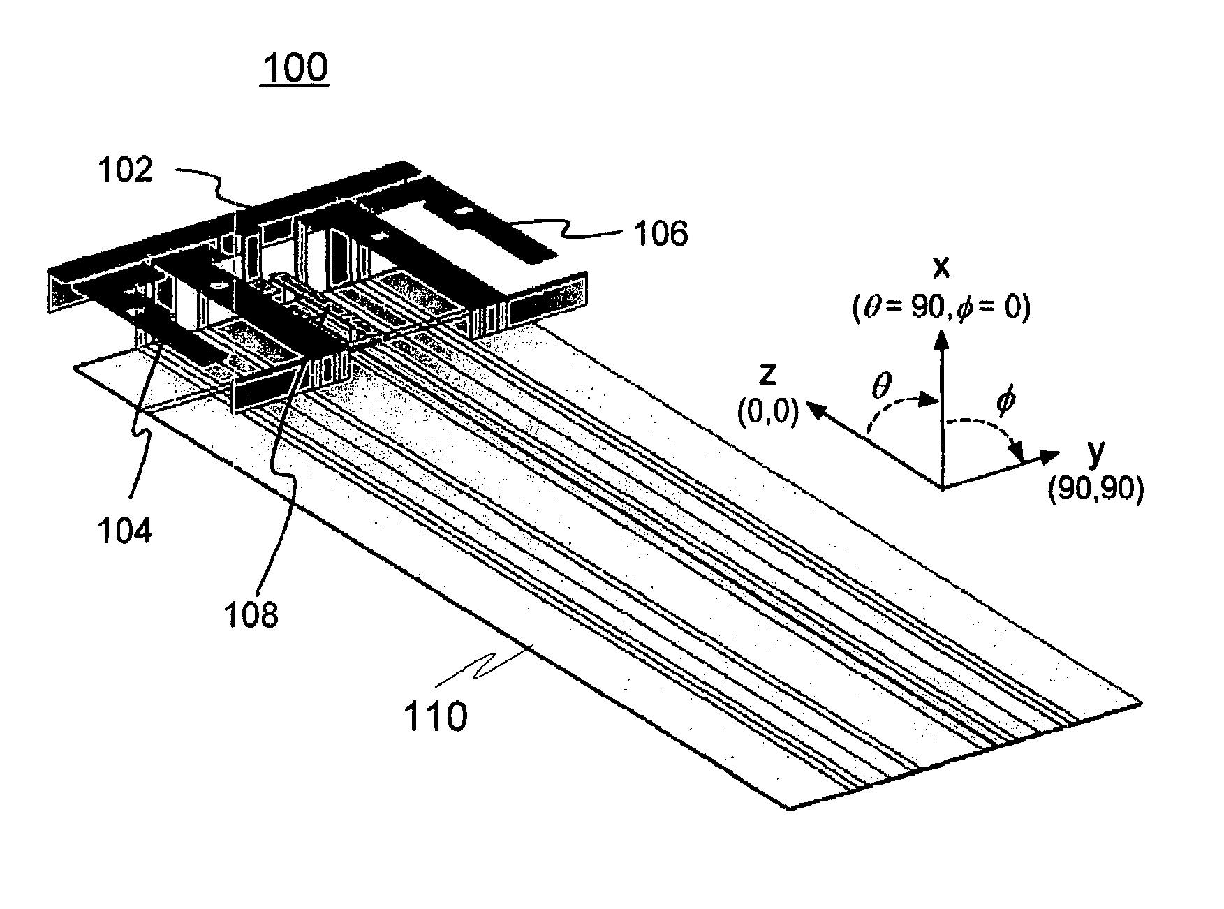
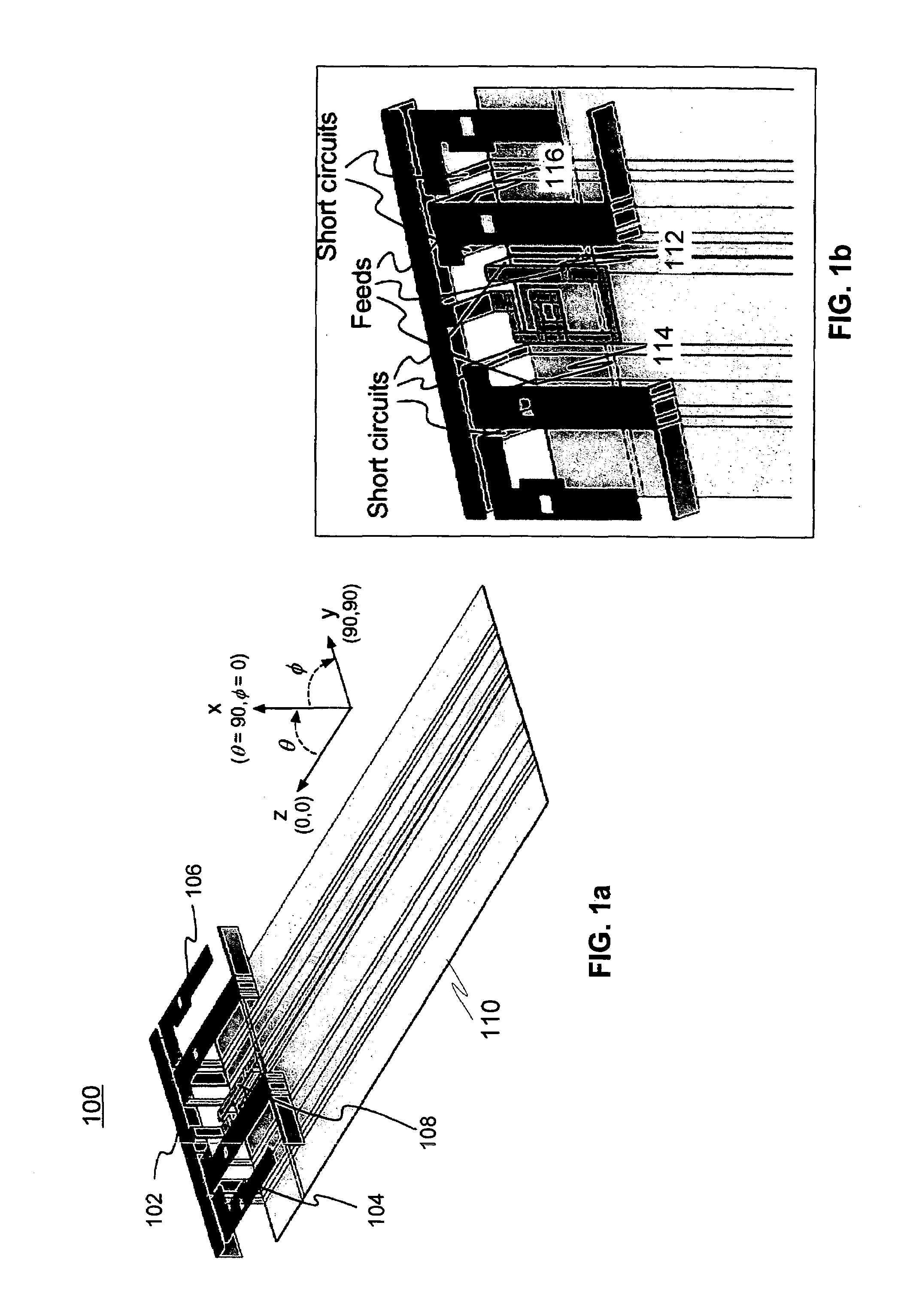
[0057]FIGS. 1a &1b illustrate a first exemplary arrangement for an antenna module 100 according to an advantageous embodiment of the invention, where the antenna module 100 consists of a separate lower band antenna 102, which is advantageously designed for the GSM850 (824-894 MHz) and E-GSM900 bands. In addition, the antenna module 100 comprises two dual-resonant coplanar shorted patch antennas 104, 106. The two dual-resonant coplanar shorted patch antennas 104, 106 are advantageously located symmetrically at the corners of the ground element 110.

[0058]In alternative embodiments the dual resonant coplanar shorted patch antennas may be any antenna element, for example it could be a resonant or non-resonant antenna element. A non-resonant antenna element may be made resonant with the use of a matching circuit and coupled to a ground plane structure. The use of a dual resonant antenna element is a preferred embodiment as this will allow operation at multiple frequency bands.

[0059]The t...


PUM


Abstract

The invention relates to a radio antenna and, more specifically, to an internal multiband antenna for use e.g. in a portable telecommunication device, such as a mobile phone. In particularly the invention relates to an antenna module for a mobile terminal including a non-resonant antenna element, two resonant antenna elements each covering at least any one of a first, second, third or fourth frequency band, said two resonant elements are substantially in the same plane and define a planar surface wherein the two resonant elements are each positioned at a corner of the planar surface and the non-resonant element is positioned along an edge of the planar surface.

Description

TECHNICAL FIELD OF THE INVENTION[0001]The invention relates to a radio antenna and, more specifically, to an internal multiband antenna for use e.g. in a portable telecommunication device, such as a mobile phone.BACKGROUND OF THE INVENTION[0002]Current wireless communication systems utilize several different radio communication standards and operate at many different frequency bands. In this fractured service environment, terminals operating in multiple systems and frequency bands offer a better service coverage than single-band and single-system terminals. One example of a multiband communication terminal is a mobile phone operating for example at four GSM bands, namely GSM850 (824-894 MHz), GSM900 (880-960 MHz), GSM1800 (1710-1880 MHz), GSM1900 (1850-1990 MHz) and further at the UMTS band (1920-2170 MHz).[0003]Compact multiband antenna configurations with good performance are needed to realize multiband mobile terminals and / or base stations. Current mobile terminals typically have...

Claims


Application Information

Patent Timeline
Patent Type & Authority Patents(United States)
IPC IPC(8): H01Q1/24H01Q1/38H01Q1/48H01Q5/00H01Q9/04H01Q5/371H01Q5/378H01Q5/40
CPCH01Q1/243H01Q9/0421H01Q9/285H01Q5/40H01Q5/371H01Q5/378H01Q21/28H01Q5/00H01Q1/24H01Q9/02H01Q9/04
Inventor OLLIKAINEN, JANILEHTOLA, ANTEROKROGERUS, JOONASRAHOLA, JUSSI
Owner RPX CORP
Why Eureka
Eureka Blog
Learn More