Image forming apparatus having fixing device with external heater

a technology of fixing device and forming apparatus, which is applied in the direction of electrographic process apparatus, instruments, optics, etc., can solve the problems of insufficient heat conductance of elastic layer, longer heating time, and less efficient heat conductivity

Inactive Publication Date: 2010-03-23
SHARP KK
View PDF15 Cites 18 Cited by
  • Summary
  • Abstract
  • Description
  • Claims
  • Application Information

AI Technical Summary

Benefits of technology

[0023]According to the arrangement, the fixing apparatus includes the release / contact operating device for moving a relative position of at least one support roller out of the support rollers with respect to the heated member between (i) a first position which allows the belt to be in contact with the heated member so that a contact area therebetween corresponds to an area where the belt and the support rollers are not in contact with each other and (ii) a second position which allows the belt to be in contact with the heated member so that the contact area is smaller than in the first position. As a result, it is possible to change the contact area (heating nip width) between the belt and the heated member, thereby controlling heat supplied from the external heating device to the heated member.
[0024]Further, according to the foregoing arrangement, the fixing apparatus includes the regulating member which is provided on the support rollers so as to be positioned axially in an outside of a region facing to the heated member. As a result, it is possible to regulate an axial position of the belt, thereby smoothly rotating the belt.
[0025]Further, the regulating member has a height from a surface of the region facing to the heated member on the support roller so that the height is longer than a distance between a surface of the support roller having the regulating member and a surface of the heated member. Thus, it is possible to prevent the regulating member from moving to the area opposite to the heated member and the support rollers, thereby appropriately controlling the contact area between the belt and the heated member.
[0027]According to the arrangement, the distance in a direction perpendicular to the common tangent line L between the tangent point P and the belt in case where said at least one support roller is in the second position is smaller than a height of the regulating member which height extends from the tangent point P to the peripheral surface of the regulating member which is in the direction perpendicular to the common tangent line L, so that it is possible to prevent the belt from running upon the regulating member even when the support rollers are moved with the belt rotated or even when the belt is rotated in the second position, thereby realizing appropriate rotation. Thus, it is possible to move the support rollers with the belt rotated, thereby adjusting heat supplied from the belt to the heated member at the same time as the image forming operation. Further, it is not necessary to stop rotation of the heated member in moving the support rollers, so that it is possible to keep the surface temperature of the heated member uniform.
[0028]An image forming apparatus of the present invention includes any one of the aforementioned fixing apparatuses. According to the arrangement, it is possible to appropriately control the temperature of the fixing apparatus.

Problems solved by technology

In the fixing roller having the elastic layer, the elastic layer cannot sufficiently conducts heat.
Thus, in case where the heating means is provided in the fixing roller, heat is less efficiently conducted, so that it takes longer time to warm up.
As a result, when the rotation of the fixing roller is stopped at the time of fixing-standby after finishing the fixing, a contact portion between the fixing roller and the external heating belt (particularly, a portion being in contact with the belt suspending roller via the external heating belt) is locally heated, so that the surface of the fixing roller has uneven temperature, which results in uneven gloss of an image.
However, in the technique of Patent Document 2, the roller is used as the external heating means, so that a contact area between the external heating means and the fixing roller is small, which results in such a problem that it is impossible to sufficiently supply heat to the fixing roller.
Thus, the arrangement in which the external heating belt can be separated from the fixing roller in order to control the surface temperature of the fixing roller raises such a problem that: the regulating member moves to a position being contact with a peripheral surface of the fixing roller, so that it is impossible to suitably control relative positions of the fixing roller and the belt thereafter.
As a result, it is impossible to supply heat from the external heating belt 103 to the fixing roller 109.
Further, the area does not allow heat to be conducted from the external heating belt 103 to the fixing roller 109, so that the area has extremely high temperature.
This results in a larger size of the fixing apparatus and in a more complicate structure of the apparatus.
As a result, it is difficult to keep the adhesive strength for an extended period of time.

Method used


Image

  • Image forming apparatus having fixing device with external heater
  • Image forming apparatus having fixing device with external heater
  • Image forming apparatus having fixing device with external heater

Examples


embodiment 1

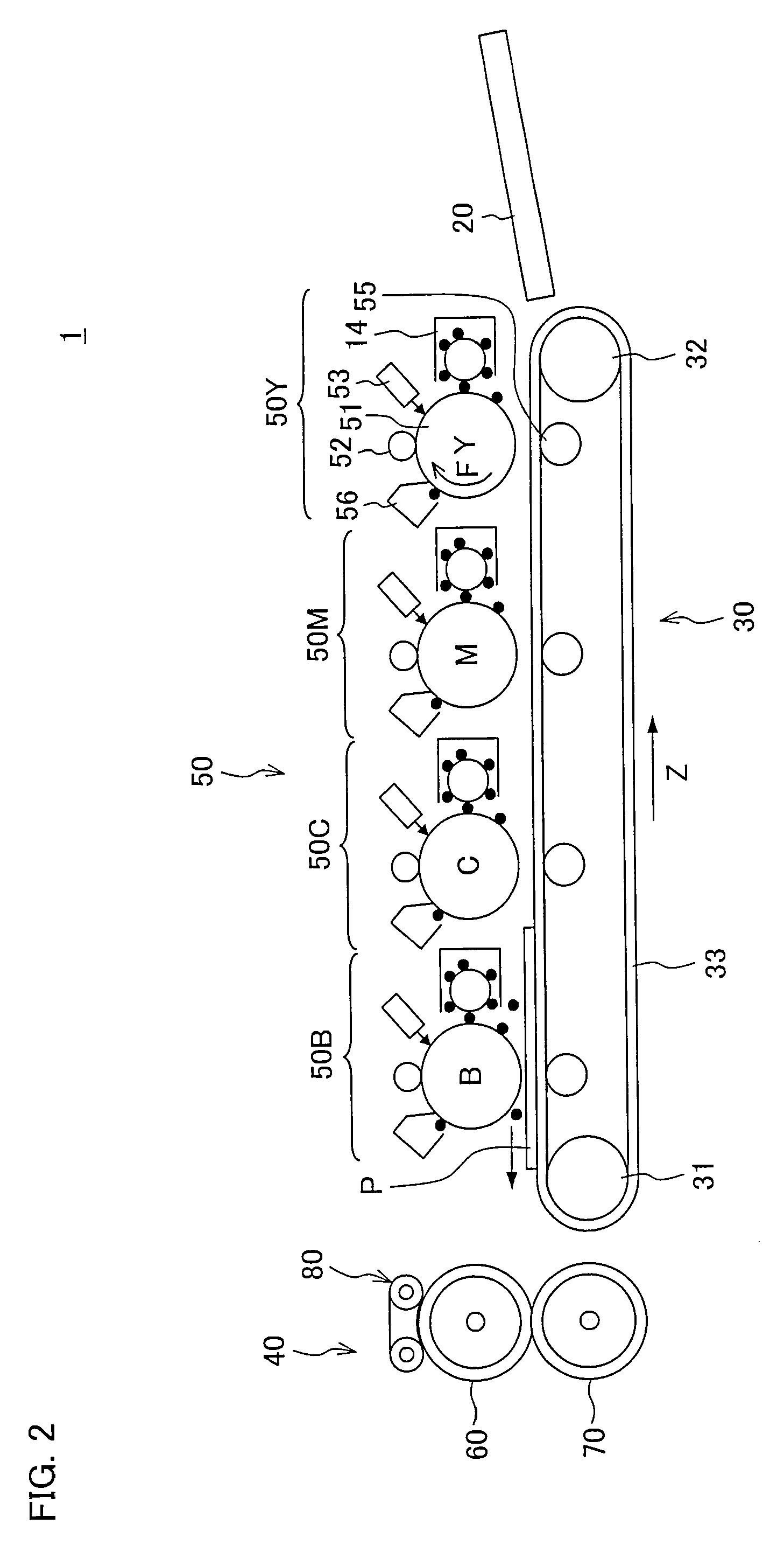
[0040]One embodiment of the present invention is described as follows. First, with reference to FIG. 2, an image forming apparatus 1 including a fixing apparatus of the present invention is described. FIG. 2 is a schematic illustrating an internal structure of the image forming apparatus 1. The image forming apparatus 1 is a dry electrophotographic color image forming apparatus and serves as a printer which for forming a color image or a monochrome image onto a sheet (recording sheet) P in accordance with image data sent from each terminal device connected via a network or image data scanned by a scanner.

[0041]The image forming apparatus 1 is a dry electrophotographic and quadruple tandem type color printer and includes a visible image transfer section 50, a sheet transport section 30, a fixing apparatus 40, a sheet feeding tray 20.

[0042]The visible image transfer section 50 includes an yellow image transfer section 50Y, a magenta image transfer section 50M, a cyan image transfer se...

embodiment 2

[0161]Another embodiment of the present invention is described as follows. Note that, for convenience in description, the same reference numerals as Embodiment 1 are given to members having the same functions as those of the members described in Embodiment 1, and descriptions thereof are omitted.

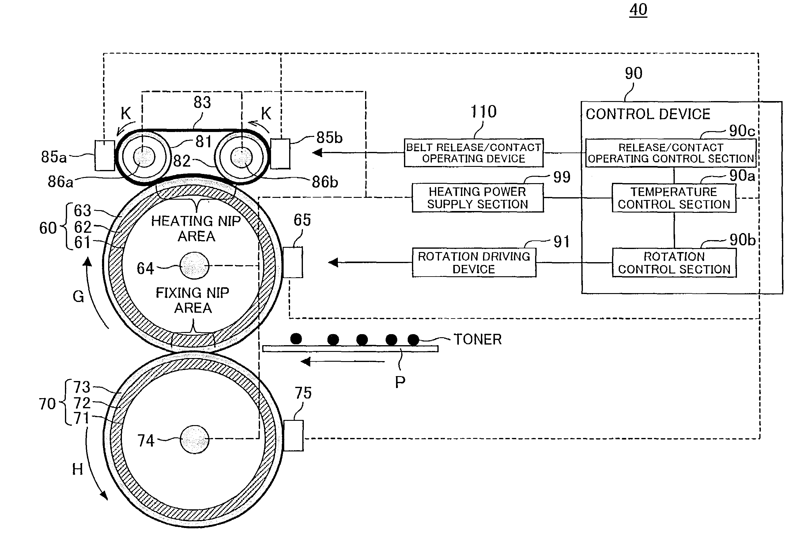
[0162]The present embodiment is different from Embodiment 1 in that there is provided an external heating device for heating the peripheral surface of the pressing roller 70. That is, the fixing apparatus 40 according to the present embodiment includes the external heating device for coming into contact with the peripheral surface of the pressing roller 70, which is in contact with the rear surface (surface having no unfixed image thereon) of the recording sheet, at the fixing nip section, so as to heat the peripheral surface of the pressing roller 70.

[0163]Each of FIGS. 9(a) and 9(b) illustrates an arrangement of the pressing roller 70 and the external heating device 130 for heating the per...


PUM


Abstract

Support rollers suspending an endless belt are arranged so that a distance between each support roller and a fixing roller is smaller than a height of a belt regulating member provided on each side of the support roller in moving the support rollers to the second position which allows the endless belt to be in contact with the fixing roller so that a contact area therebetween is smaller than in the first position. As a result, in a fixing apparatus which includes the regulating member for regulating a position of an external heating belt in a rotational axis direction so that a contact area size between the external heating belt and the fixing member is variable, it is possible to appropriately vary the contact area between the belt and the fixing material.

Description

[0001]This Nonprovisional application claims priority under 35 U.S.C. § 119(a) on Patent Application No. 067292 / 2006 filed in Japan on Mar. 13, 2006, the entire contents of which are hereby incorporated by reference.FIELD OF THE INVENTION[0002]The present invention relates to (i) a fixing apparatus used in an electrophotographic image forming apparatus and (ii) an electrophotographic image forming apparatus using the fixing apparatus.BACKGROUND OF THE INVENTION[0003]Generally, as a fixing apparatus used in an electrophotographic image forming apparatus such as a copying machine, a printer, and the like, a heat roller type fixing apparatus is frequently used. The heat roller type fixing apparatus includes a fixing roller and a pressing roller which are pressed against each other, wherein heating means constituted of a halogen lamp (halogen heater) disposed in the fixing roller or halogen lamps (halogen heaters) disposed in both the rollers heats the pair of rollers at a predetermined...

Claims


Application Information

Patent Timeline
Patent Type & Authority Patents(United States)
IPC IPC(8): G03G15/20
CPCG03G15/2032G03G2215/2016G03G2215/2019
Inventor ASAKURA, KENJIYAMAJI, HIROYUKI
Owner SHARP KK
Why Eureka
Try Eureka