Wire harness interconnection and retention method and apparatus

a technology of interconnection and wire harness, which is applied in the direction of electrical equipment, line/current collector details, contact members penetrating/cutting insulation/cable strands, etc., can solve the problems of time-consuming stripping of insulation and interconnections which exhibit less than ideal electrical characteristics

Inactive Publication Date: 2010-03-30
KORRUS INC
View PDF16 Cites 14 Cited by
  • Summary
  • Abstract
  • Description
  • Claims
  • Application Information

AI Technical Summary

Problems solved by technology

Such procedures have been recognized by the inventors to involve time-consuming stripping of insulation and interconnections which exhibit less than ideal electrical characteristics.

Method used


Image

  • Wire harness interconnection and retention method and apparatus
  • Wire harness interconnection and retention method and apparatus
  • Wire harness interconnection and retention method and apparatus

Examples


Embodiment Construction

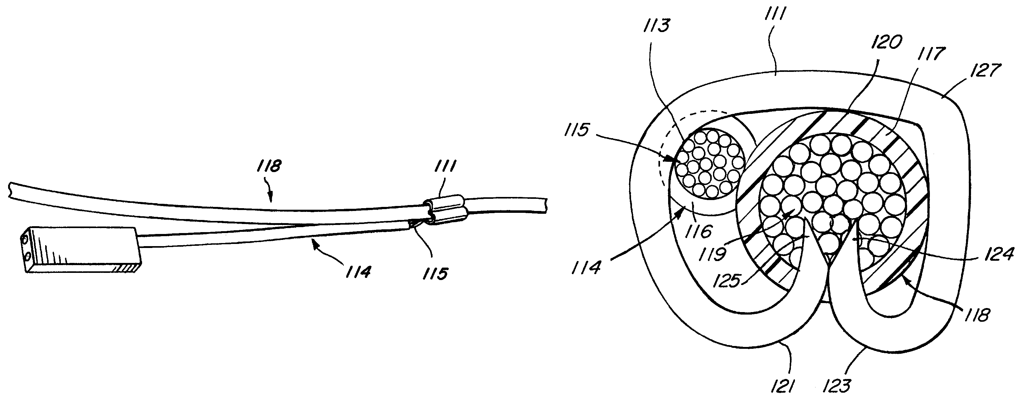
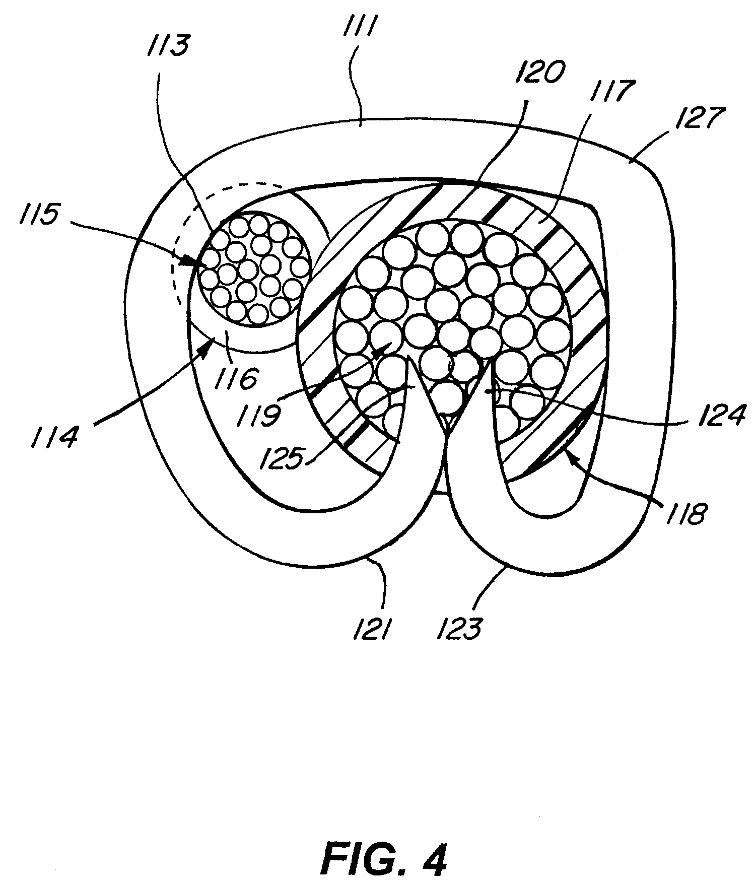
[0016]According to an illustrative embodiment, a larger electrical conductor 118, for example, a 16 gauge wire, is joined to a smaller electrical conductor 14, for example, a 26 or 18 gauge wire, using a metal connecting band 111, which may be, for example, a thin brass strip.

[0017]The smaller electrical conductor 114 has a short portion of its outer plastic insulation 116 removed at one end thereof for a length of, for example, approximately ⅛ inch. The exposed metal conductor wire 115 is then placed adjacent to the larger electrical conductor 118 such that the exposed metal wire 115 of the smaller conductor 114 makes physical contact with the plastic insulation 117 of the larger conductor 118.

[0018]The metal band 111 is then placed on top of these two conductors 114, 118 and then is wrapped down and around both sides of the conductors 114, 118, holding them firmly in place and establishing metal to metal contact between the band 111 and the exposed metal wire 115 portion of the sm...


PUM

PropertyMeasurementUnit
conductiveaaaaaaaaaa
insulatingaaaaaaaaaa
electricalaaaaaaaaaa

Abstract

A smaller conductor having an uninsulated portion and an insulated portion is positioned adjacent a larger conductor having an insulated portion and a conductive portion located within the insulated portion of the larger conductor. The two conductors are joined by a discontinuous metal band having respective ends extending across a top portion of the insulated portion of the larger conductor to make electrical contact with the uninsulated portion of the smaller conductor, then bending downward on one side of the conductor pair and then upward and through the insulated portion of the larger conductor such that a first of the ends of the metal band is positioned in contact with the conductive portion of the larger conductor; the metal band bending downward on the opposite side of the conductor pair and then upward and through the insulated portion of the larger conductor such that a second of the ends of the metal band is positioned in contact with the conductive portion of the larger conductor.

Description

RELATED APPLICATIONS[0001]This application claims the benefit of and priority to U.S. Provisional Application Ser. No. 61 / 033,346, filed Mar. 3, 2008, entitled “Wire Harness Interconnection and Retention Method and Apparatus,” the contents of which are incorporated by reference herein in its entirety.FIELD[0002]The subject invention relates generally to wire interconnection apparatus and methods and more particularly to a method of more simply and economically establishing an electrical connection between adjacent conductors, as well as a “clam shell” harness retainer for adjacent interconnected pairs of wires.RELATED ART[0003]Procedures are known in the art for interconnecting adjacent bare portions of metal conductors. Such procedures have been recognized by the inventors to involve time-consuming stripping of insulation and interconnections which exhibit less than ideal electrical characteristics.SUMMARY[0004]A smaller conductor having an uninsulated portion and an insulated port...

Claims


Application Information

Patent Timeline
Patent Type & Authority Patents(United States)
IPC IPC(8): H01R4/24
CPCH01R4/183H01R4/2495Y10T29/49201Y10T29/5193
Inventor PEARSON, DENNISHORWITZ, TERRY
Owner KORRUS INC
Why Eureka
Try Eureka