High energy density piezoelectric ceramic materials

a piezoelectric ceramic and high energy density technology, applied in piezoelectric/electrostrictive/magnetostrictive devices, basic electric elements, generators/motors, etc., can solve the problems of high cost, tediousness, and technology driven, and achieve high energy density, improved piezoelectric characteristics, and high energy density

Inactive Publication Date: 2010-03-30
BOARD OF RGT THE UNIV OF TEXAS SYST
View PDF13 Cites 9 Cited by
  • Summary
  • Abstract
  • Description
  • Claims
  • Application Information

AI Technical Summary

Problems solved by technology

Unfortunately, integration of these methods with an intended platform of “small-range” and / or “energy-on-demand” has proven to be expensive, tedious as well as technology-driven.

Method used


Image

  • High energy density piezoelectric ceramic materials
  • High energy density piezoelectric ceramic materials
  • High energy density piezoelectric ceramic materials

Examples


examples

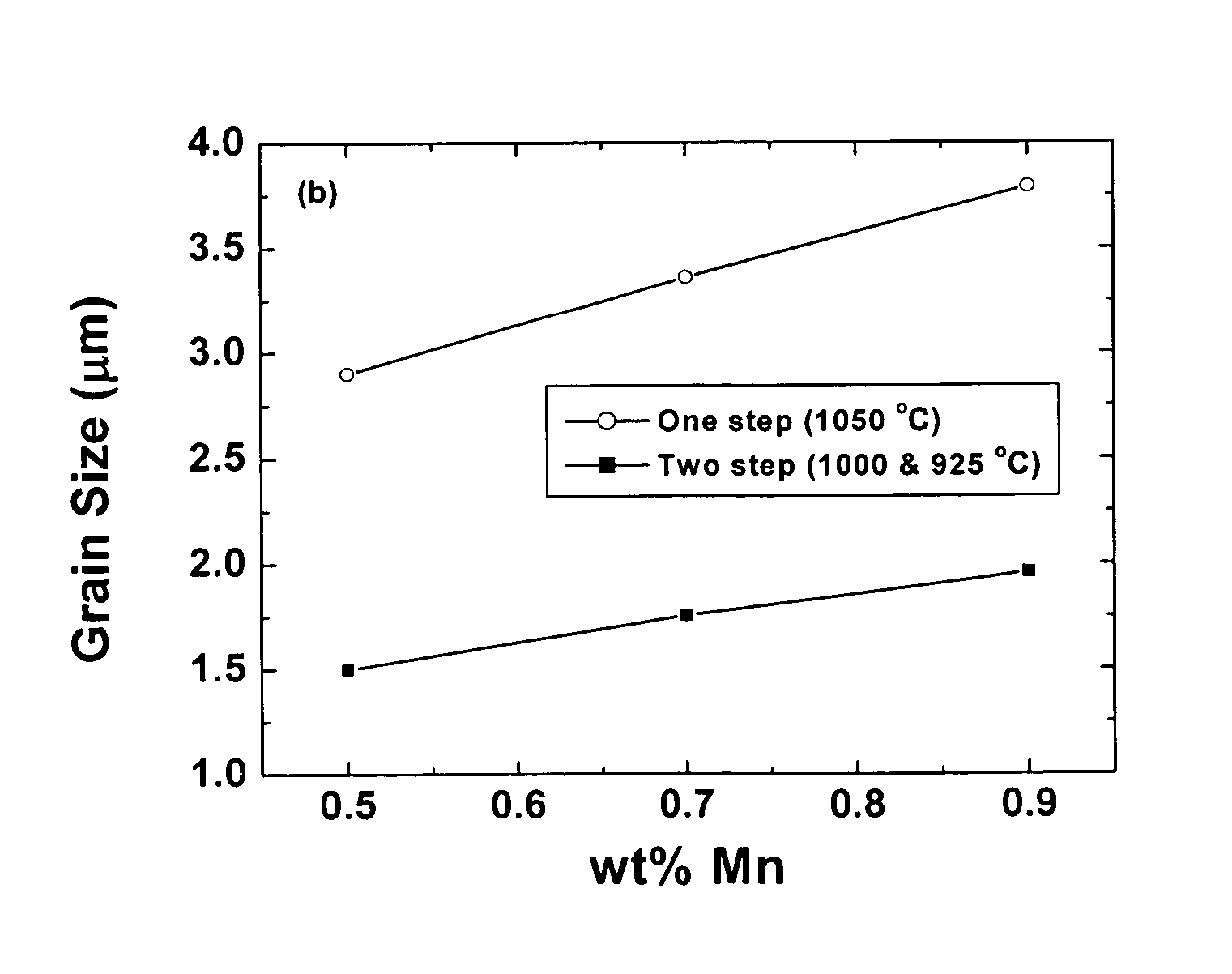
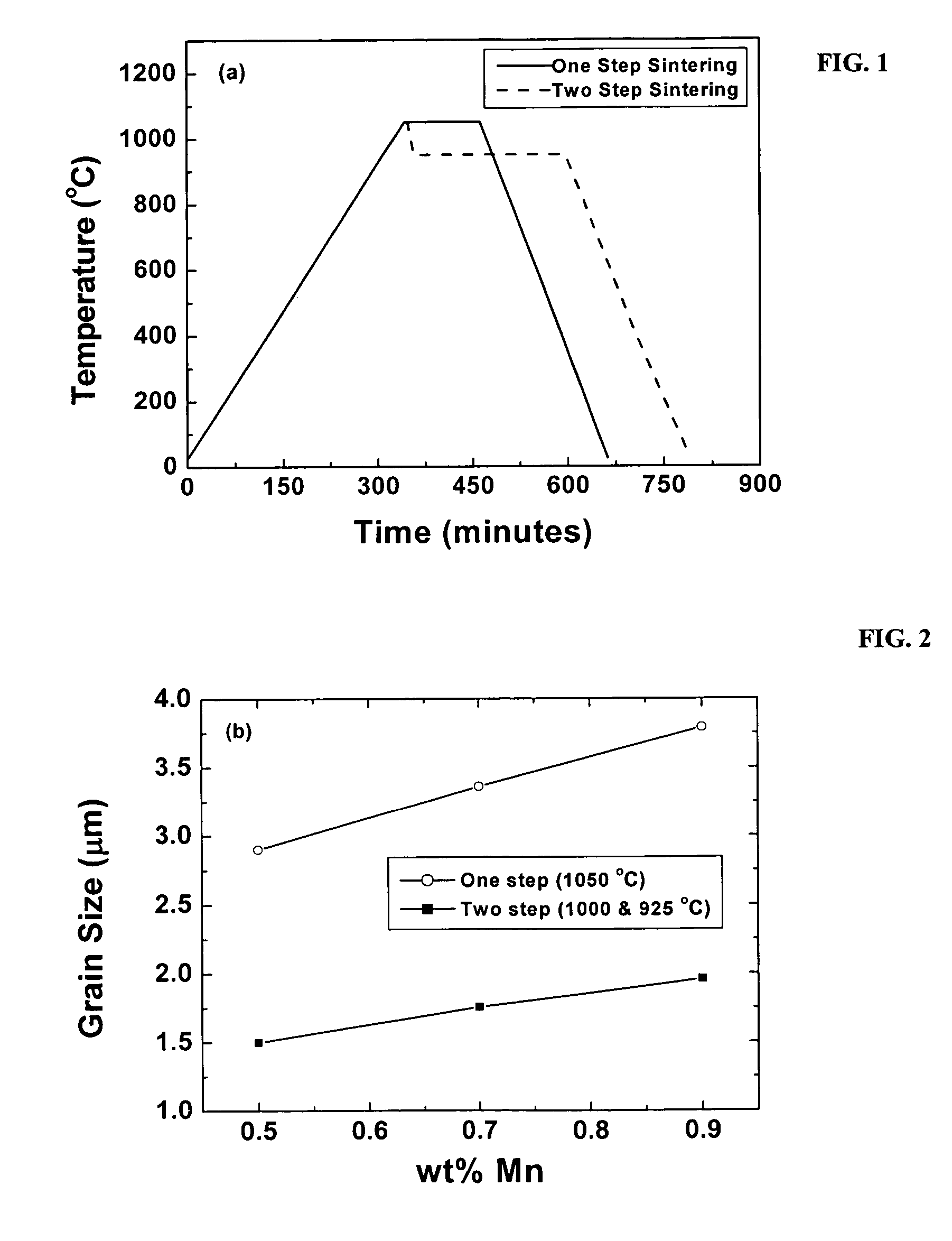
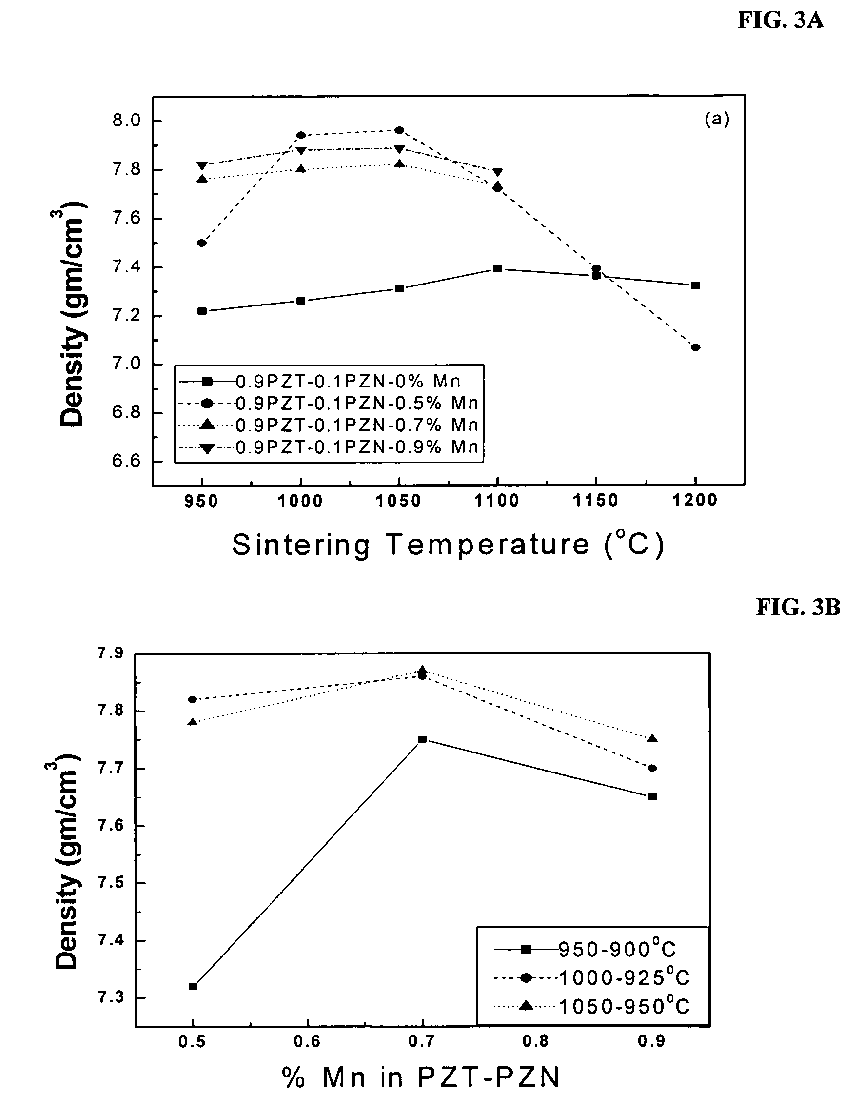
[0049]A preferred sintering profile was obtained by preparing a polycrystalline ceramic composition comprising 0.9 Pb(Zr0.52Ti0.48)O3−0.1 Pb(Zn1 / 3Nb2 / 3)O3+0.5, 0.7 and 0.9 wt % manganese carbonate (MnCO3) using two different sintering profiles: a single step process (a conventional process that includes sintering at about 1050° C. for 2 hrs) and a two step process. For the two step sintering, samples were kept at about 900° C. or higher for at least about five minutes followed by a temperature drop, wherein the drop was from 25 degrees to over 100 degrees. In one example, samples were kept at 1000° C. for at least about five minutes followed by a temperature drop to about 925° C. which was held for about 4 hours. In another example, samples were first kept at 950° C. followed by a temperature drop to about 900° C. In another example, samples were first kept at 1050° C. followed by a temperature drop to about 950° C. A heating rate of 3° C. / min and cooling rate of 7° C. / min was typic...


PUM


Abstract

The present invention includes methods, devices, and compositions having improved piezoelectric characteristics with high energy density. Compositions of the present invention are ceramic materials of the formula: Pb[(Zr0.52Ti0.48)O3]1−x[(Zn1 / 3Nb2 / 3)O3]x+Mn, where x is 0.05 to 0.20 and Mn is manganese in a form that is present from about 0.1 to 1.5 wt %. Suitable manganese forms as the starting material include MnCO3, MnO2, MnO, and Mn3O4. The compositions exhibit a high product of piezoelectric voltage constant and piezoelectric stress constant. The compositions are polycrystalline or textured with a dense microstructure and small grain. The piezoelectric voltage constant and piezoelectric stress constant obtained from such compositions are superior to those of conventional hard or soft ceramics and yield a magnitude product of the piezoelectric voltage constant and piezoelectric stress constant that is significantly higher than those reported in the literature or in available with commercial or conventional ceramic compositions.

Description

BACKGROUND OF THE INVENTION[0001]The present invention relates generally to improved ceramic materials with high energy density, in particular, polycrystalline and textured ceramic materials with improved electric and piezoelectric behaviors suitable for harvesting and producing energy and in energy sensing devices.[0002]The search high efficiency smart structures for energy harvesting in both defense and civil applications is ongoing, particularly in the area of small integrated structures. Research efforts have focused on on-site generators for unmanned aerial and water vehicles, hybrid automobiles, smart pocket computers, audio and video devices. Previous efforts have involved generating energy via solar energy, hydrogen fuel cell, thermoelectric devices and photostrictive materials. Unfortunately, integration of these methods with an intended platform of “small-range” and / or “energy-on-demand” has proven to be expensive, tedious as well as technology-driven. A more attractive al...

Claims


Application Information

Patent Timeline
Patent Type & Authority Patents(United States)
IPC IPC(8): C04B35/493H01L41/187
CPCC04B35/493H01L41/1136H01L41/1876H02N2/18C04B2235/3262C04B2235/3263C04B2235/3265C04B2235/3267C04B2235/3284C04B2235/661C04B2235/81H10N30/306H10N30/8554
Inventor PRIYA, SHASHANK
Owner BOARD OF RGT THE UNIV OF TEXAS SYST
Why Eureka
Try Eureka