
Control of small distributed energy resources

a distributed energy resource and small technology, applied in the direction of emergency power supply arrangements, transportation and packaging, dc network circuit arrangements, etc., can solve the problems of large-scale power interruptions, life-threatening consequences of hospital power interruptions, and aging transmission and distribution systems that remain subject to occasional failures, etc., to increase the unit output power

Active Publication Date: 2010-03-30
WISCONSIN ALUMNI RES FOUND
View PDF20 Cites 34 Cited by
  • Summary
  • Abstract
  • Description
  • Claims
  • Application Information

AI Technical Summary

Problems solved by technology

At the same time, aging transmission and distribution systems remain subject to occasional failures.
Massive failures covering wide geographical areas and affecting millions of people have occurred, even in the United States which has historically enjoyed a relatively robust electrical power system.
These problems with the capacity and reliability of the public power grid have driven the development of distributed energy resources (DER), small independent power generation and storage systems which may be owned by, and located near, consumers of electrical power.
For example, an interruption of power to a hospital can have life-threatening consequences.
Similarly, when power to a factory is interrupted, the resulting losses, for example in productivity, wasted material in process that must be scrapped, and other costs to restart a production line, can be catastrophic.
Geographically distributed sources of power, such as wind, solar, or hydroelectric power, may be too limited or intermittent to be used as the basis for a centralized power plant.
Because of fundamental differences between distributed energy resources, such as inverter based microsources or small synchronous generators, and centralized energy resources, these existing methods are not suitable to allow distributed energy resources to smoothly and efficiently transition between island mode and grid mode as the distributed energy resources join and separate from the main power grid.
Even if the independent producers of power are able to communicate with each other, there may not be any effective way to ensure that they cooperate.

Method used


Image

  • Control of small distributed energy resources
  • Control of small distributed energy resources
  • Control of small distributed energy resources

Examples


Embodiment Construction

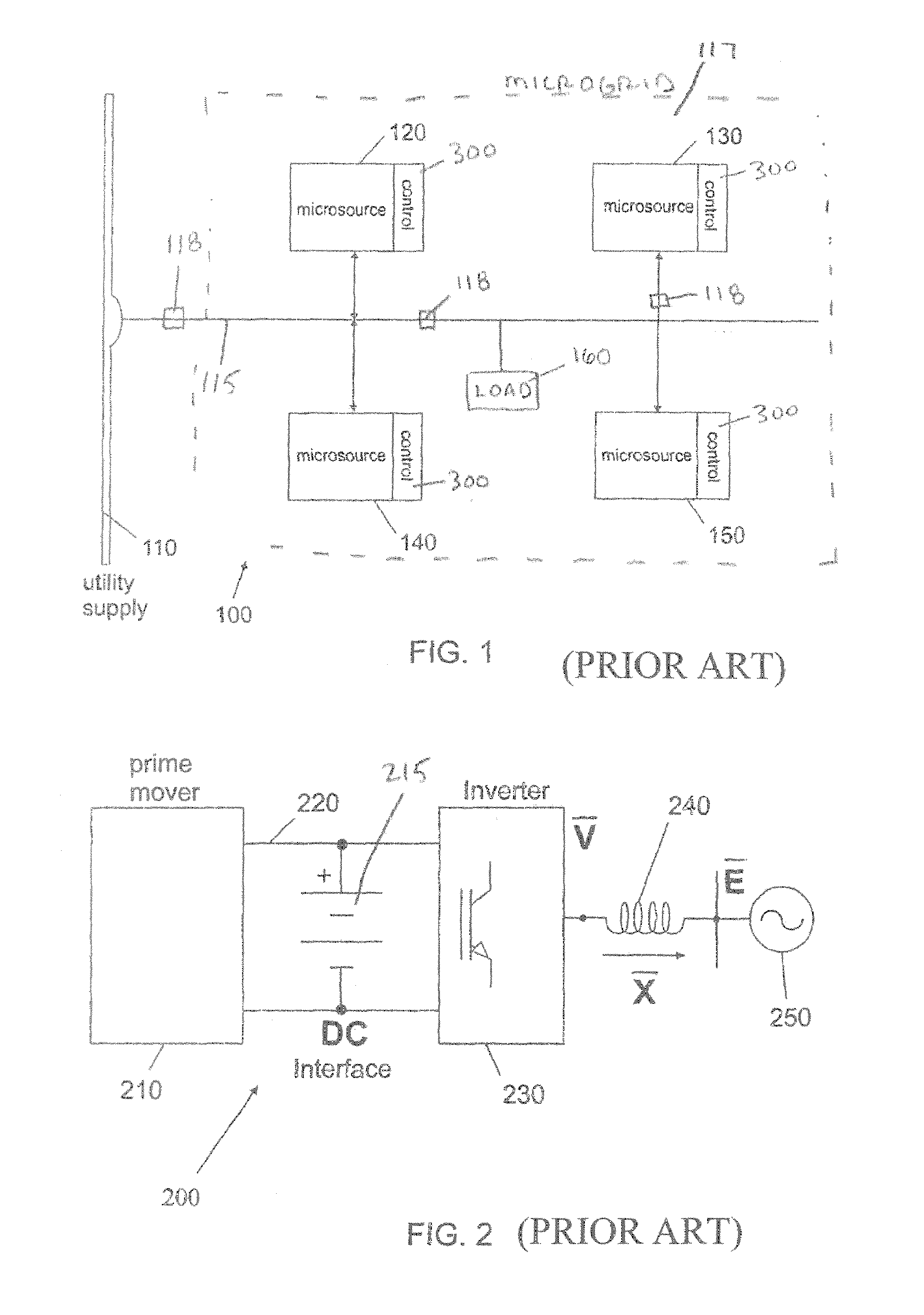
[0056]Referring to the figures, FIG. 1 is a diagram of an exemplary distributed energy resource system. Such an exemplary system is described, for example, in U.S. Patent Application Publication No. US 2004 / 0051387, the contents of which are incorporated by reference. In the event of any conflict between the disclosure of the present application and the disclosure of U.S. Patent Application Publication No. US 2004 / 0051387, the disclosure of the present application controls.

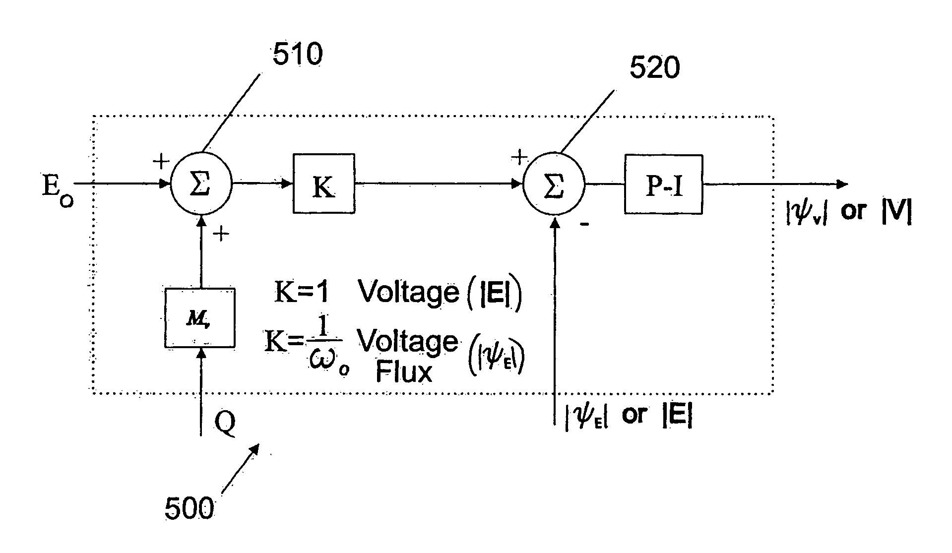
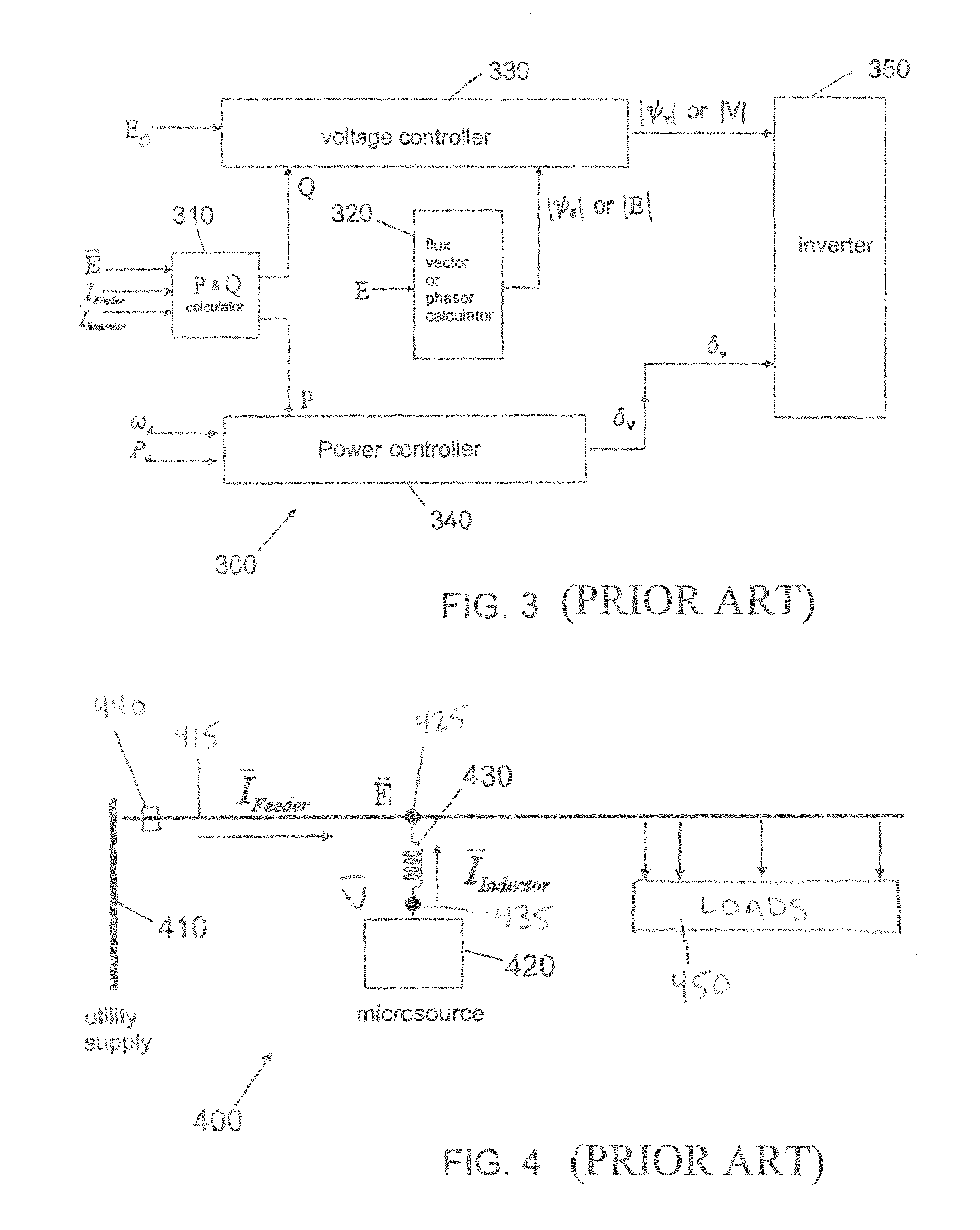
[0057]The present invention relates to a system for and method of control of small distributed energy resources. This control can be implemented by changing the phase of the output from the microsource as a function of time, to vary the instantaneous frequency and power of that output.

[0058]The invention relates more particularly to novel control schemes for controlling the instantaneous frequency and power from one or more microsources in ways that tend to ensure that the microsources stay within their normal ope...


PUM


Abstract

A method of controlling the output inverter of a microsource in a distributed energy resource system is disclosed. Embodiments of the invention include using unit or zone power controllers that reduce the operating frequency of the inverter to increase its unit output power. Preferred embodiments includes methods wherein the inverter reaches maximum output power and minimum operating frequency at the same time, and further comprising using a voltage controller implementing a voltage vs. reactive current droop. Other aspects of this embodiment relate to an inverter that implements such methods, and a microsource containing such an inverter. These methods can be extended to control inverters in a plurality of microsources, organized in a single zone or in a plurality of zones.

Description

REFERENCE TO GOVERNMENT RIGHTS[0001]This invention was made with U.S. government support awarded by the following agencies:[0002]DOE DE-AC03-76SF00098[0003]NSF 0119230[0004]The U.S. has certain rights in this invention.FIELD OF THE INVENTION[0005]The present invention relates generally to power systems and methods, including distributed energy resources (DER) systems and methods, and more particularly to devices and methods for controlling small distributed energy resources and / or associated loads.BACKGROUND OF THE INVENTION[0006]In the U.S. and around the world, the demand for electrical power continues to grow. At the same time, aging transmission and distribution systems remain subject to occasional failures. Massive failures covering wide geographical areas and affecting millions of people have occurred, even in the United States which has historically enjoyed a relatively robust electrical power system. These problems with the capacity and reliability of the public power grid h...

Claims


Application Information

Patent Timeline
Patent Type & Authority Patents(United States)
IPC IPC(8): H02J3/00
CPCH02J3/38H02J2003/388H02J3/388
Inventor LASSETER, ROBERT H.PIAGI, PAOLO
Owner WISCONSIN ALUMNI RES FOUND
Learn More