Power amplifier and radio wave transmitter having the same

a technology of power amplifier and radio wave transmitter, which is applied in the direction of gated amplifier, gain control, baseband system details, etc., can solve the problems of quantization noise, output signal deterioration in snr, and modulated signal having a larger papr encountering larger difficulties in increasing the power efficiency of a power amplifier

Active Publication Date: 2010-10-21
NEC CORP
View PDF5 Cites 107 Cited by
  • Summary
  • Abstract
  • Description
  • Claims
  • Application Information

AI Technical Summary

Benefits of technology

[0037]a low-pass filter for removing high-frequency noise from an output signal of the switching amplifier;
[0057]As a result, since the output signal of the AD converter presents a substantially constant SNR at all times, the power amplifier can generate an output signal with a substantially constant SNR at all times.
[0058]For the reasons set forth above, the power amplifier can advantageously maintain the SNR of its output signal substantially constant at all times independently of the average power of the output signal.

Problems solved by technology

As such, a modulated signal having larger PAPR encounters larger difficulties in increasing the power efficiency of a power amplifier.
However, since the polar modulation type power amplifiers shown in FIGS. 1 and 2 convert an envelope signal to a time discrete signal which is quantified through AD conversion, quantization noise occurs.
Particularly, the output signal tends to deteriorate in SNR when a power amplifier generates an output signal with reduced average power.

Method used


Image

  • Power amplifier and radio wave transmitter having the same
  • Power amplifier and radio wave transmitter having the same
  • Power amplifier and radio wave transmitter having the same

Examples


first embodiment

[0083]FIG. 4 shows the configuration of power amplifier 10 according to a first embodiment of the present invention.

[0084]As shown in FIG. 4, power amplifier 10 of this embodiment comprises AD converter 11, switching amplifier 12, low-pass filter 13, power controller 14, a plurality of high-frequency power amplifiers 15-1˜15-n (n is an integer given by n≧2), and modulated signal output terminal 16.

[0085]AD converter 11 is applied with an envelope signal which includes only an amplitude modulated component of a high-frequency modulated signal for use in radio communications for conversion of the same to a time discrete signal.

[0086]Switching amplifier 12 amplifies the output signal of AD converter 11.

[0087]Low-pass filter 13 removes high-frequency noise from the output signal of switching amplifier 12.

[0088]Each of the plurality of high-frequency power amplifiers 15-1˜15-n are supplied with the output signal of low-pass filter 13 as a power supply, and used for amplifying a carrier s...

second embodiment

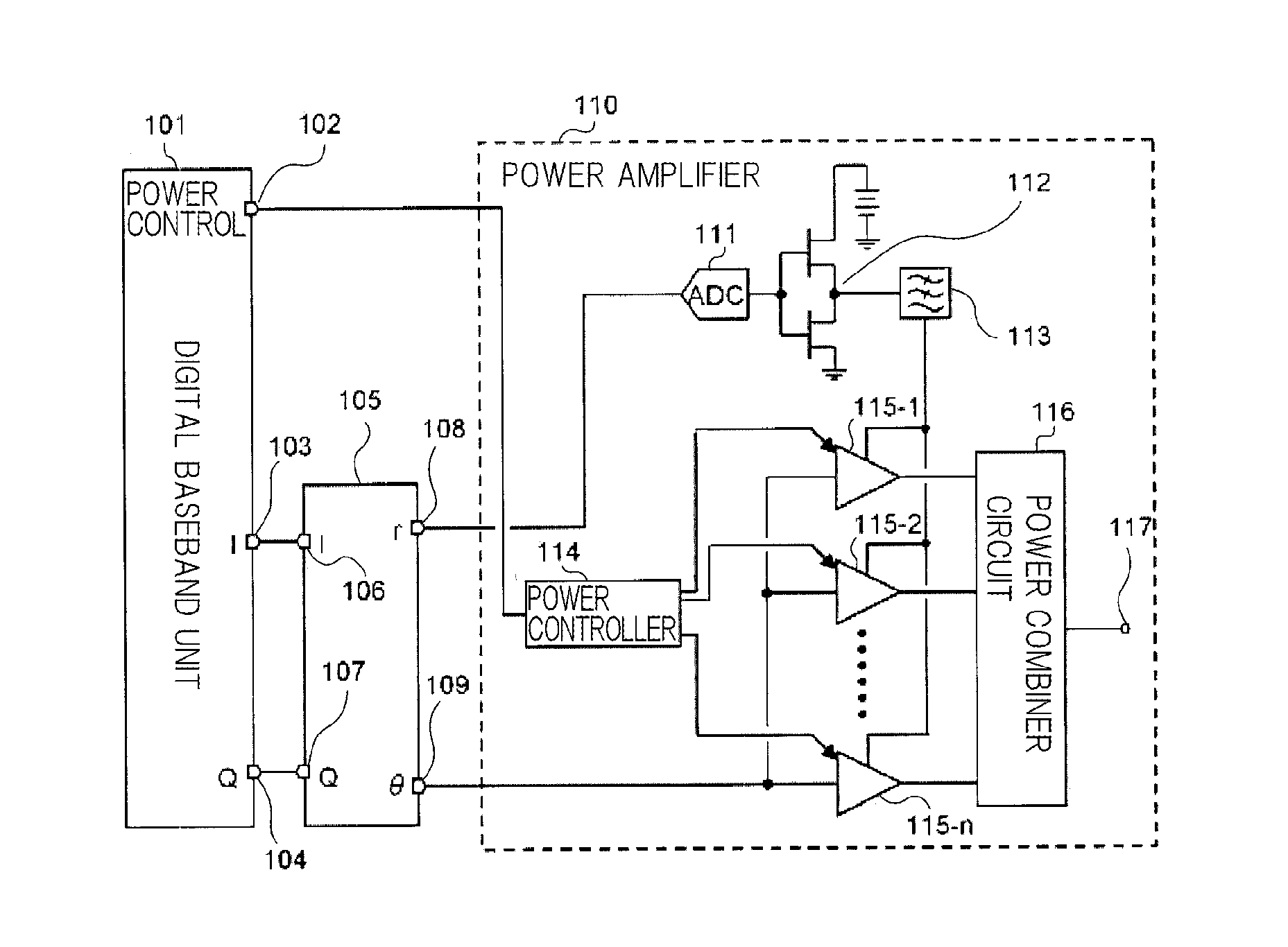
[0099]FIG. 6 shows the configuration of a radio wave transmitter which comprises power amplifier 110 according to a second embodiment of the present invention.

[0100]The radio wave transmitter shown in FIG. 6 comprises digital baseband unit 101, polar coordinate conversion circuit 105, and power amplifier 110.

[0101]Digital baseband unit 101 in turn comprises power control signal output terminal 102, I-signal output terminal 103, and Q-signal output terminal 104. Polar coordinate conversion circuit 105 in turn comprises I-signal input terminal 106, Q-signal input terminal 107, envelope signal output terminal 108, and phase modulated signal output terminal 109. Power amplifier 110 in turn comprises AD converter 111, switching amplifier 112, low-pass filter 113, power controller 114, high-frequency power amplifiers 115-1˜115-n (n is an integer given by n≧2), power combiner circuit 116, and modulated signal output terminal 117.

[0102]Digital baseband unit 101 generates a power control sig...

third embodiment

[0116]A power amplifier according to a third embodiment of the present invention is modified such that the average power of the output signal can be adjusted by a method other than the on / off control of high-frequency power amplifiers 115-1˜115-n, as performed in the second embodiment.

[0117]FIG. 7 shows the configuration of a radio wave transmitter which comprises power amplifier 410 according to the third embodiment of the present invention.

[0118]The radio wave transmitter shown in FIG. 7 comprises digital baseband unit 401, polar coordinate conversion circuit 405, and power amplifier 410, as is the case with the second embodiment.

[0119]Digital baseband unit 401 in turn comprises power control signal output terminal 402, I-signal output terminal 403, and Q-signal output terminal 404. Polar coordinate conversion circuit 405 in turn comprises I-signal input terminal 406, Q-signal input terminal 407, envelope signal output terminal 408, and phase modulated signal output terminal 409. ...


PUM


Abstract

A power amplifier (10) comprises: an A / D converter (11) for converting, to a time discrete signal, an envelope signal included in a high-frequency modulated signal and including only an amplitude modulated component of the high-frequency modulated signal; a switching amplifier (12) for amplifying the output signal of the A / D converter (11); a low-pass filter (13) for removing high frequency noise from the output signal of the switching amplifier (12); a plurality of high-frequency power amplifiers (15-1 to 15-n) for receiving the output signal of the low-pass filter (13) as a power supply and for amplifying a carrier signal included in the high-frequency modulated signal; and a power controller (14) for adjusting the average power of the output signal of the power amplifier (10) by controlling the total gains of the plurality of high-frequency power amplifiers (15-1 to 15-n).

Description

TECHNICAL FIELD[0001]The present invention relates to a power amplifier and a radio wave transmitter having the same, and particularly, to a power amplifier and a radio wave transmitter having the same, which do not entail a change in SNR (Signal to Noise Ratio) of an output signal even if an average power of the output signal is changed.BACKGROUND ART[0002]In recent years, radio communications, such as those based on portable telephones and the like, employ a modulation scheme which demonstrates a high frequency utilization efficiency and a large peak-to-average power ratio (PAPR).[0003]In the field of radio communications, for amplifying a modulated signal including an amplitude modulated component using an AB-class amplifier which has been conventionally employed, sufficient back-off must be taken in order to maintain the linearity of an output signal. Generally, this back-off is required to be at least in the order of PAPR.[0004]On the other hand, the AB-class amplifier exhibits...

Claims


Application Information

Patent Timeline
Patent Type & Authority Applications(United States)
IPC IPC(8): H04L27/00H03G3/30
CPCH03F2203/21136H03F2200/451H03F2203/21196H03F2203/7215H03F2203/7236H03G3/004H03G3/3042H03F1/0222H03F1/0277H03F3/19H03F3/211H03F3/245H03F3/72H03F2200/336H03F2203/21142
Inventor TAKAHASHI, KIYOHIKO
Owner NEC CORP
Why Eureka
Try Eureka