Token based power control mechanism

a technology of power control mechanism and token, applied in the direction of program control, liquid/fluent solid measurement, instruments, etc., can solve the problems of not providing an adequate balance between system performance and effective power distribution

Active Publication Date: 2008-10-23
GLOBALFOUNDRIES US INC
View PDF17 Cites 112 Cited by
  • Summary
  • Abstract
  • Description
  • Claims
  • Application Information

AI Technical Summary

Problems solved by technology

However, typical power management techniques do not effectively manage the power distribution in a system, and usually do not provide an adequate balance between system performance and power management.

Method used


Image

  • Token based power control mechanism
  • Token based power control mechanism
  • Token based power control mechanism

Examples


Embodiment Construction

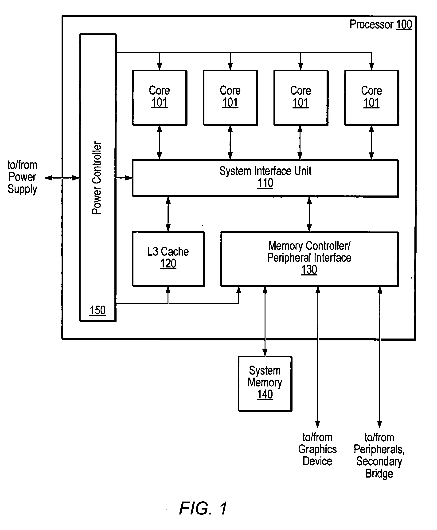
[0014]Turning now to FIG. 1, a block diagram of one embodiment of an exemplary processor 100 is shown. A processor implementation may include multiple instances of a processing core fabricated as part of a single integrated circuit along with other structures. As shown, in one specific implementation, processor 100 may include four processing cores 101a-d, each of which may be configured as described below with reference to FIG. 5. In the illustrated embodiment, each of cores 101 may couple to an L3 cache 120 and a memory controller / peripheral interface unit (MCU) 130 via a system interface unit (SIU) 110. In one embodiment, L3 cache 120 may be configured as a unified cache, implemented using any suitable organization, that operates as an intermediate cache between L2 caches of cores 101 and relatively slow system memory 140.

[0015]MCU 130 may be configured to interface processor 100 directly with system memory 140. For example, MCU 130 may be configured to generate the signals neces...


PUM


Abstract

A token-based power control mechanism for an apparatus including a power controller and a plurality of processing devices. The power controller may detect a power budget allotted for the apparatus. The power controller may convert the allotted power budget into a plurality of power tokens, each power token being a portion of the allotted power budget. The power controller may then assign one or more of the plurality of power tokens to each of the processing devices. The assigned power tokens may determine the power allotted for each of the processing devices. The power controller may receive one or more requests from the plurality of processing devices for one or more additional power tokens. In response to receiving the requests, the power controller may determine whether to change the distribution of power tokens among the processing devices.

Description

BACKGROUND OF THE INVENTION[0001]1. Field of the Invention[0002]This invention relates to power management techniques and, more particularly, to a token-based power control mechanism.[0003]2. Description of the Related Art[0004]Power management techniques in electronic systems may not only reduce the power consumption of the system but may also improve the system performance. In various systems, a predetermined amount of power is provided to each of the different devices within the system. The system may include a power controller and a monitoring mechanism to monitor the power provided to each of the devices to prevent the power supply from providing too much power to any one device. For instance, the monitoring mechanism may detect when a power limit has been exceeded in one of the devices and may initiate, in conjunction with the power controller, corrective actions to decrease the power supplied to the device. Also, the monitoring mechanism may detect when a device is in a sleep...

Claims


Application Information

Patent Timeline
Patent Type & Authority Applications(United States)
IPC IPC(8): G06F1/26
CPCG06F9/3017G06F9/3853Y02B60/1239G06F9/30149G06F9/3851G06F1/3243G06F9/3842G06F1/3287G06F9/3891Y02B60/1278G06F9/3885G06F1/3203Y02B60/1282G06F9/383Y02D10/00
Inventor MEIER, STEPHANEVERS, MARIUS
Owner GLOBALFOUNDRIES US INC
Why Eureka
Try Eureka