Method and system for control of turbogenerator power and temperature

a technology of turbogenerator and power supply, which is applied in the direction of electric generator control, machines/engines, transportation and packaging, etc., can solve the problems of reduced fuel efficiency, limited fuel efficiency, and increased efficiency of turbine operation, so as to maximize the efficiency of the turbine and increase the speed of the turbine

Inactive Publication Date: 2005-10-25
CAPSTONE TURBINE
View PDF9 Cites 114 Cited by
  • Summary
  • Abstract
  • Description
  • Claims
  • Application Information

AI Technical Summary

Benefits of technology

[0003]In one aspect, the invention provides a method and apparatus for controlling the turbine of a turbine powered generating system regardless of the load on the system to maximize the efficiency of the turbine, where the turbine has a fixed nozzle geometry and the system further includes an electrical generator and a storage device. The method and apparatus comprises maintaining the inlet nozzle at a substantially constant temperature and using the electrical generator to satisfy the first power demand on the system until th

Problems solved by technology

The operating efficiency of a turbine typically increases along with the fuel combustion temperature, which is most often limited by the materials used to construct

Method used


Image

  • Method and system for control of turbogenerator power and temperature
  • Method and system for control of turbogenerator power and temperature
  • Method and system for control of turbogenerator power and temperature

Examples


Embodiment Construction

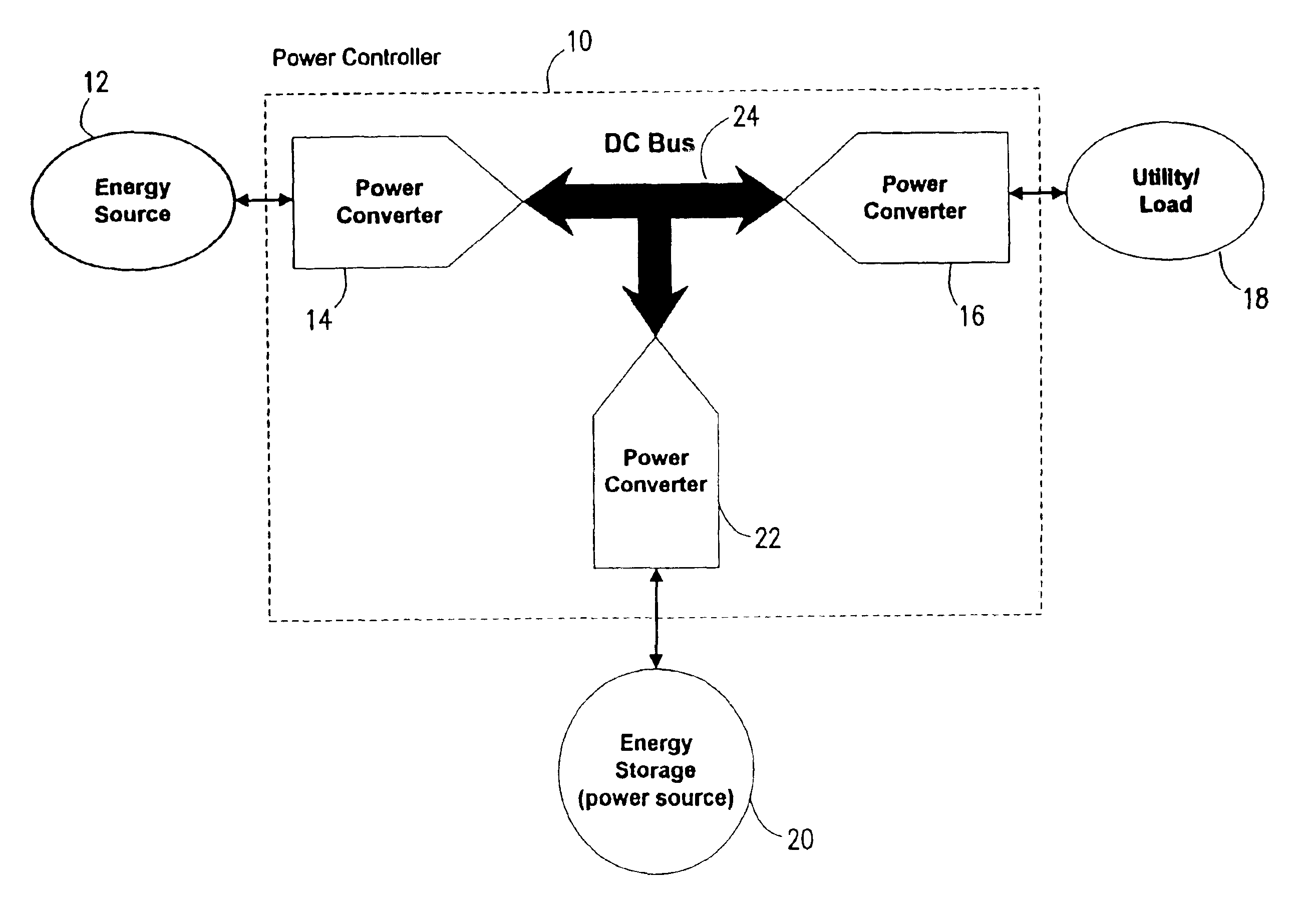
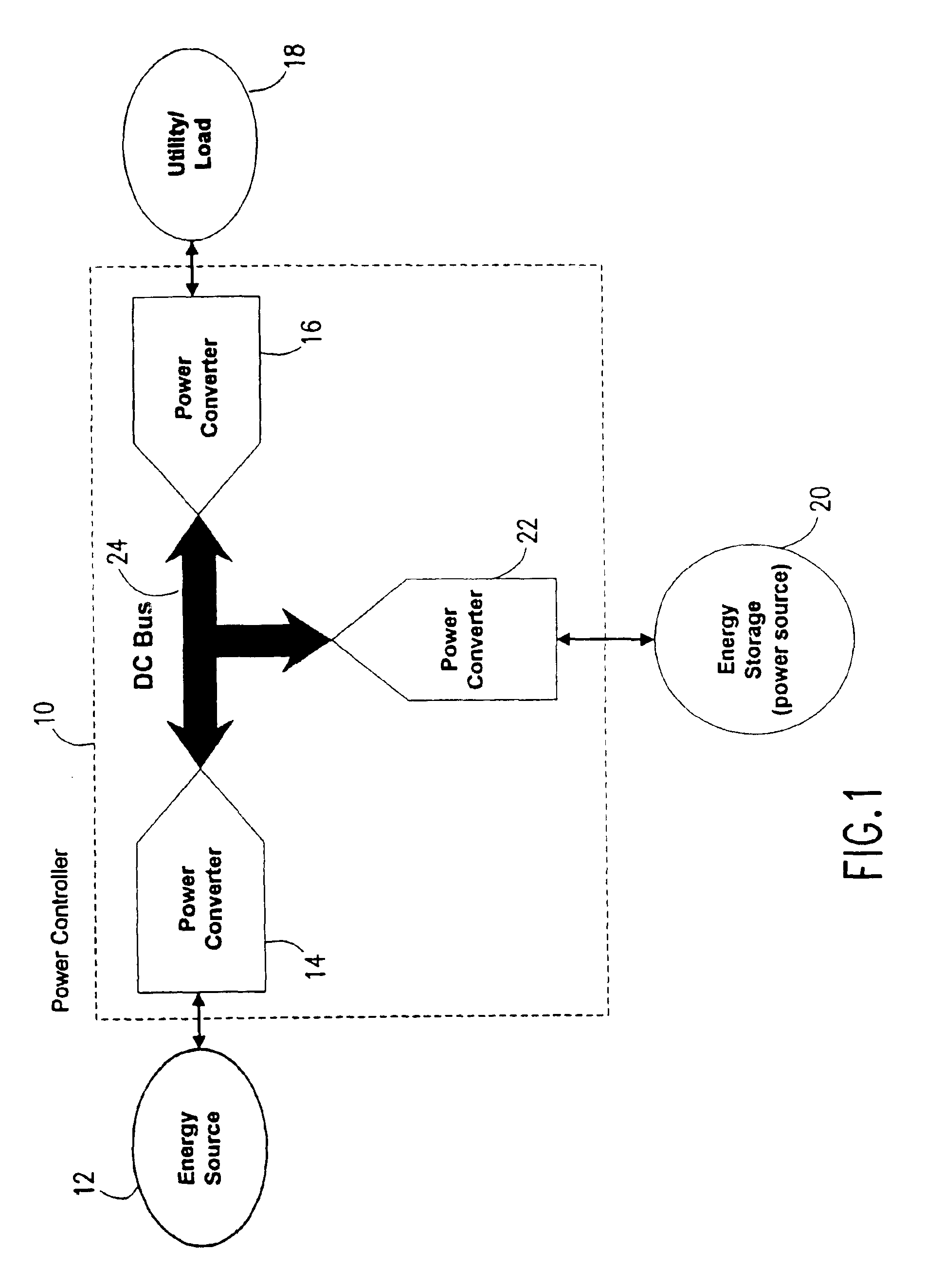
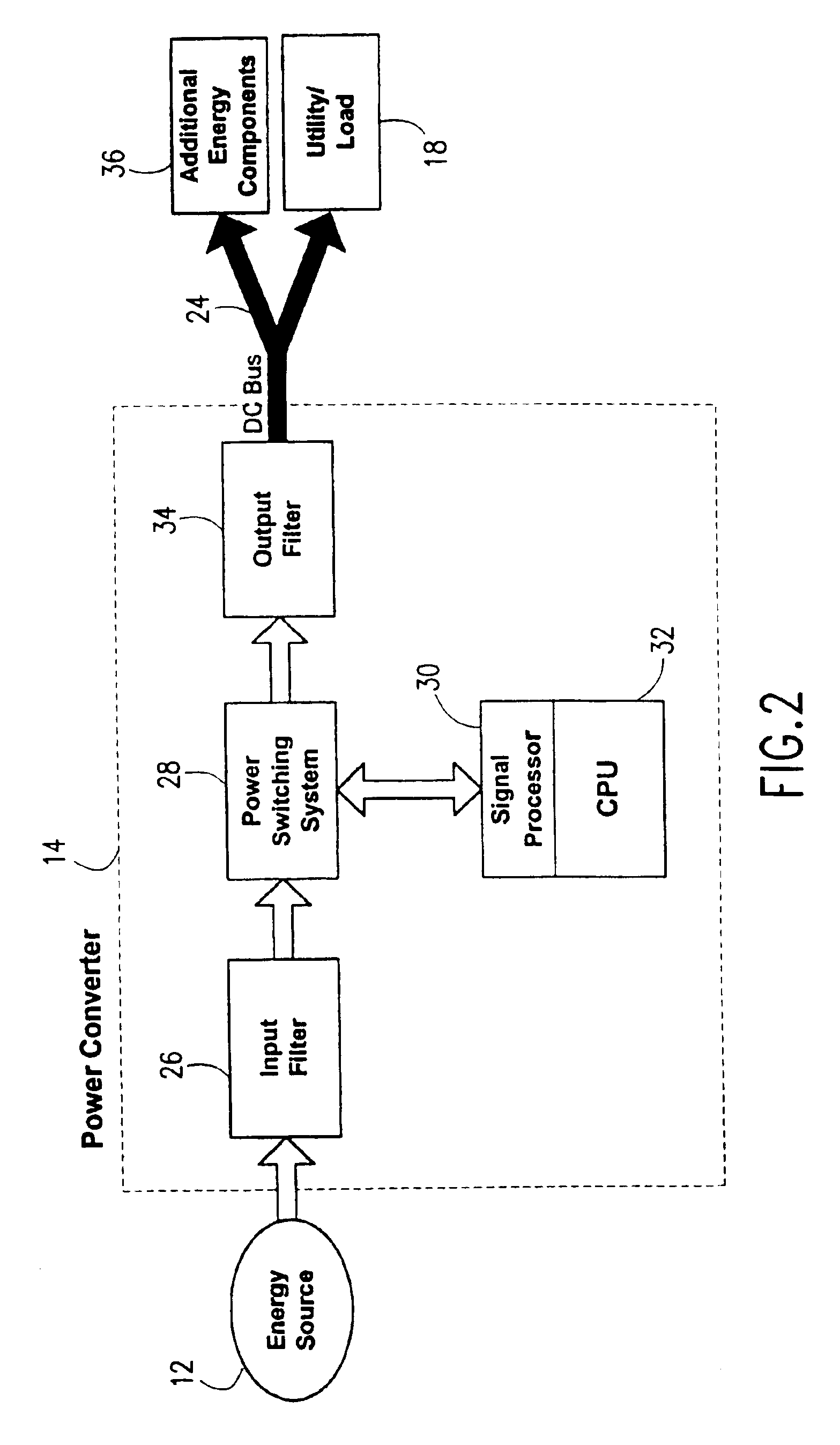
[0028]Referring to FIG. 1, power controller 10 provides a distributed generation power networking system in which bi-directional (i.e. reconfigurable) power converters are used with a common DC bus for permitting compatibility between one or more energy components. Each power converter operates essentially as a customized bi-directional switching converter configured, under the control of power controller 10, to provide an interface for a specific energy component to DC bus 24. Power controller 10 controls the way in which each energy component, at any moment, will sink or source power, and the manner in which DC bus 24 is regulated. In this way, various energy components can be used to supply, store and / or use power in an efficient manner.

[0029]One skilled in the art will recognize that the particular configurations shown herein are for illustrative purposes only. In particular, the present invention is not limited to the use of three bi-directional converters as shown in FIG. 1. R...


PUM


Abstract

A power controller controls the turbine of a turbine powered generating system regardless of the load on the system to maximize the efficiency of the turbine and maintains the turbine at a substantially constant temperature during a system load change by using an energy storage device to provide power to the load while the turbine is changing speed to meet the new load demand.

Description

RELATED APPLICATIONS[0001]This application is a continuation of, and claims the benefit of the filing date of, application Ser. No. 10 / 037,916, filed on Jan. 2, 2002, now U.S. Pat. No. 6,870,279 which, in turn, is a continuation-in-part, and claims the benefit of the filing date of, application Ser. No. 09 / 207,817 filed on Dec. 8, 1998, now U.S. Pat. No. 6,487,096 which claims the benefit of U.S. Provisional Application No. 60 / 080,457, filed on Apr. 2, 1998; and which is a continuation-in-part, and claims the benefit of the filing date of, the reissue application of U.S. Pat. No. 6,031,294 filed on Dec. 31, 2001, Ser. No. 10 / 039,819.BACKGROUND OF THE INVENTION[0002]The operating efficiency of a turbine typically increases along with the fuel combustion temperature, which is most often limited by the materials used to construct the combustor components such as the fuel inlet nozzle or nozzles. It is therefore usually desirable to operate a turbine at or near the maximum temperature l...

Claims


Application Information

Patent Timeline
IPC IPC(8): H02J1/14H02J1/10
CPCH02J1/10H02J1/14
Inventor GILBRETH, MARKWACKNOV, JOELWALL, SIMON
Owner CAPSTONE TURBINE
Why Eureka
Try Eureka