
Dual type multiple stage, hydraulic turbine power generator including reaction type turbine with adjustable blades

Inactive Publication Date: 2002-06-13
ELLIOTT CO
View PDF0 Cites 14 Cited by
  • Summary
  • Abstract
  • Description
  • Claims
  • Application Information

AI Technical Summary

Benefits of technology

[0004] The basic concept of the present invention is the incorporation of a plurality of reaction type turbine stages arranged in serial fashion on the single shaft for the hydraulic turbine power generator with the output stage of the hydraulic turbine being responsive to the fluid flow discharged from the input turbine stage or stages and being characterized as having a plurality of adjustable blades that permit the pitch of the blades to be adjusted for varying the fluid flow through the output stage to achieve a substantially constant speed for the single shaft mounting the hydraulic turbine and electrical power generator and maximizing the efficiency of the turbine. The input turbine can be a Francis type turbine stage of single or a plurality of stages while the output turbine stage can be a Kaplan type turbine stage.
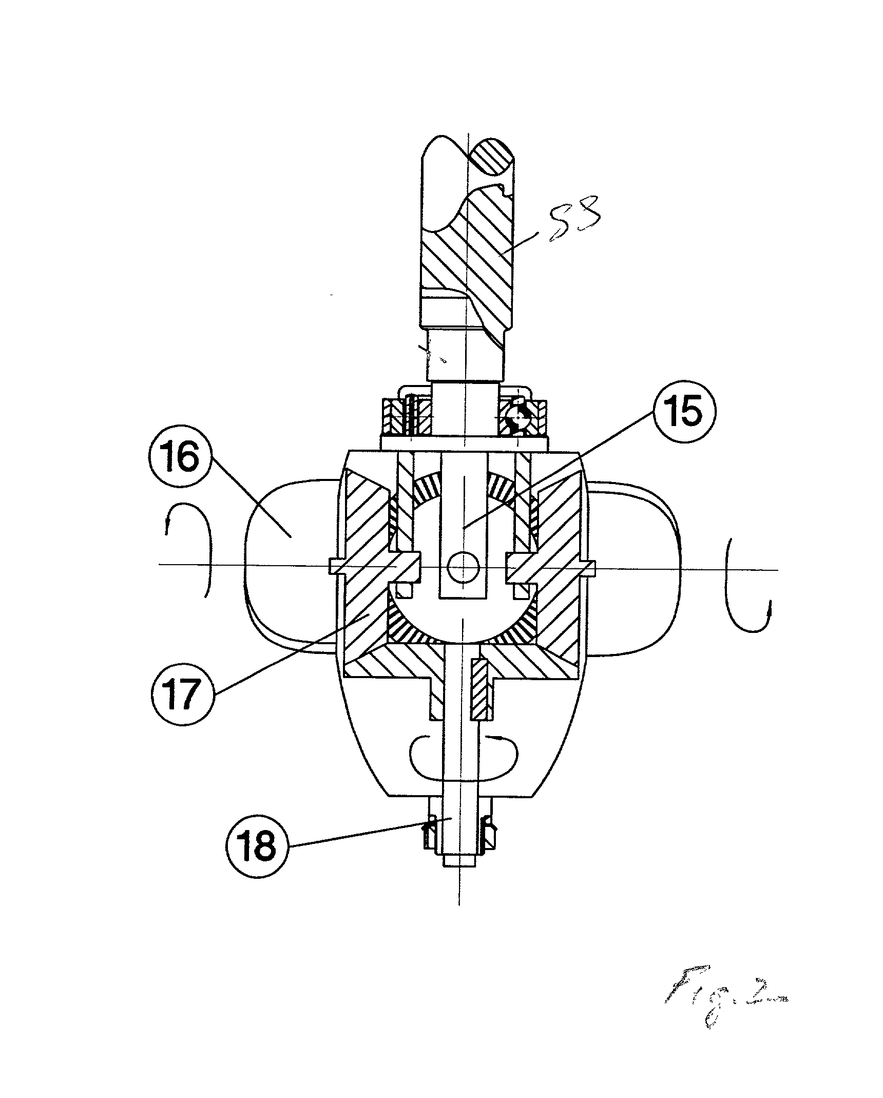
[0005] In accordance with the present invention the adjustable pitch blades can be rotated to any desired position by either statically moving the blades when the turbine is inoperative or by dynamically adjusting the turbine blades when the turbine is operative. In the disclosed static adjustment of the adjustable turbine vanes, the hydraulic turbine mounts a supporting structure adjacent the fluid discharge end thereof for mounting an electrical motorized device operable to extend a keyed blade for adjustment purposes. A gear drive system is imbedded into Kaplan style turbine runner for controlling the pitch of the runner blades of the Kaplan style turbine runner so that the efficiency of the turbine can be fine tuned. The keyed blade is adapted to fit into a positioning shaft controlling the movements of the gear drive system. This static adjustment is accomplished while the turbine is inoperable and when the adjustment is complete, the keyed blade is retracted and the turbine is in condition to be operated at the adjusted pitch for the runner blades.
[0007] The use of the turbine with adjustable blades is also advantageous when the source of hydraulic fluid is in two phases, namely a liquid and gas / vapor mixture. In this embodiment, a turbine expander is used for permitting pressure reduction into the vapor phase but takes advantage of the buoyant and convective forces of released gas or vapor by routing the fluid in a vertical direction such that the fluid is aided by these forces as contrasted with the reverse or downward, conventional flow. The reverse fluid flow mixture through the turbine causes the rise of the bubbles of released gas or vaporized liquid aids the primary fluid flow. The entire hydraulic turbine electrical power generator is arranged in a closed container with suitable fluid inlet and a separate fluid outlet and gas / vapor outlet so as to function as a separator of the gas / vapor from the liquid.

Problems solved by technology

Experience with the patented hydraulic power generator has resulted in that the need for the variable speed, constant frequency controller, identified in the above identified prior patent as element IS, has produced problems due to the operational problems due encountered with the commercially available controller IS.
This problem has resulted in the desirability of providing a hydraulic turbine power generator and more particularly submersible hydraulic turbine power generator operative with preselected hydraulic fluids that eliminates the need for the use of the variable speed, constant frequency controller to thereby provide a power generator free of the frequency controller problems.

Method used


Image

  • Dual type multiple stage, hydraulic turbine power generator including reaction type turbine with adjustable blades
  • Dual type multiple stage, hydraulic turbine power generator including reaction type turbine with adjustable blades
  • Dual type multiple stage, hydraulic turbine power generator including reaction type turbine with adjustable blades

Examples


Embodiment Construction

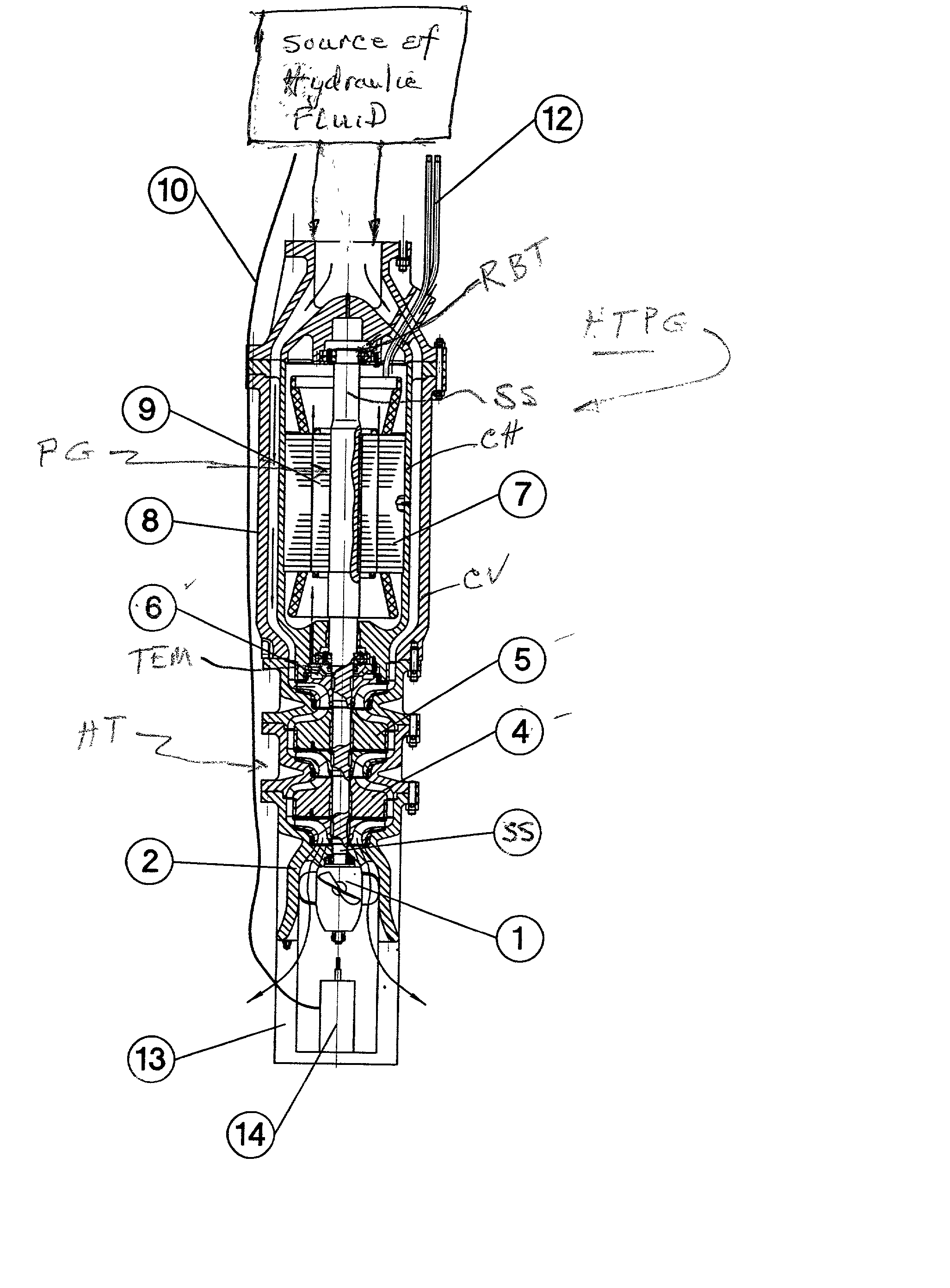
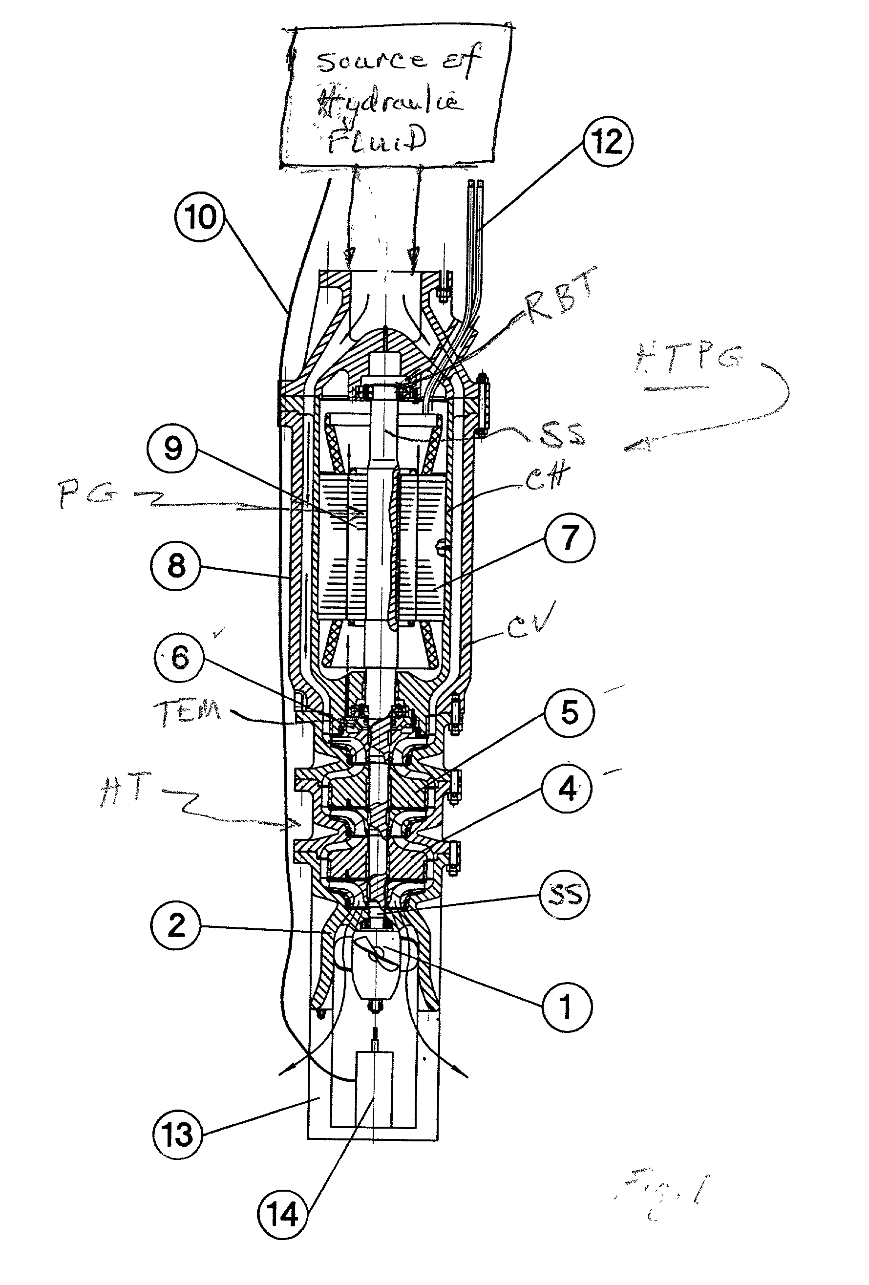
[0018] Now referring to the drawings, the hydraulic turbine electrical power generator of the present invention operative at a preselected single speed and thereby a single electrical frequency for the generated electrical power will be described in detail. The hydraulic turbine electrical power generator HTPG is illustrated in the drawings and will be described for use as a submerged hydraulic turbine power generator HTPG to be operative as a submerged hydraulic turbine generator HT to be operative in response to cryogenic, liquefied gases coupled to the hydraulic turbine. The hydraulic turbine HT and the electrical power generator PG are both mounted on a single shaft SS. For the purposes of the present invention, the terms "hydraulic fluids" or "hydraulic fluid flow" is an operative hydraulic fluid for operating the hydraulic turbine HT and cooling the electrical power generator PG are electrically, non-conductive fluids, including cryogenic liquefied gases, such as liquefied nat...


PUM


Abstract

A hydraulic turbine power generator mounted on a single shaft wherein the hydraulic turbine means includes a plurality of reaction type turbine stages arranged to be in combination, rotatably responsive to the hydraulic fluid coupled to the turbines. One of the turbine stages having axial turbine runner means mounted to the single shaft and having a plurality of adjustable blades for permitting the pitch of the blades to be adjusted for controlling the effective operative fluid head to cause the shaft to rotate at a preselected speed and including means for adjusting the pitch of the adjustable blades. The turbine stages can be a Francis type turbine and a Kaplan type turbine. The hydraulic turbine power generator can be oriented in an upward direction to cause the fluid flow to travel upwardly through the turbine stages and function as a two phase turbine expander resulting in the separation of the liquid phase from the gas / vapor stage.

Description

[0001] Hydraulic Turbine Power Generator incorporating a plurality of Reaction type turbine stages including a turbine stage with adjustable blades for maximizing turbine efficiency and controlling the output electrical frequency of the power generator.BACKGROUND OF INVENTION[0002] This invention is an improvement of the Hydraulic Turbine Power Generator that is the subject of the Weiser U.S. Pat. No. 5,659,205, assigned to the same assignee as the present invention. The hydraulic turbine of U.S. Pat. No. 5,659,205 is operable with a hydraulic fluid source that has a variable flow rate and a high pressure and is converted by the turbine structure to a relatively high fluid velocity. The turbine runner blades disclosed in the prior patent are fixed, axial runner blades so that the rotary speeds imparted to the single shaft mounting the hydraulic turbine and power generator is operative at a variable, rotary speeds. The power generator is provided with a variable frequency exciting cu...

Claims


Application Information

Patent Timeline
IPC IPC(8): F03B3/02F03B3/04F03B3/06F03B3/14F03B13/08F03B13/10F03B15/04F03B15/06F03B15/08F03B15/20
CPCF03B3/02F03B3/06F03B13/105Y02E10/226Y02E10/22Y02E10/223F03B15/04Y02E10/20
Inventor HYLTON, EVERETT
Owner ELLIOTT CO
Learn More