Rust removing and paint spraying device for inner wall of pipeline

A technology for pipes and paint spraying equipment, applied in the directions of spraying device, liquid spraying device, grinding drive device, etc., can solve the problems of large amount of paint, large elastic potential energy, uneven painting on the inner wall of the pipeline, etc., and achieve the effect of even painting

Active Publication Date: 2017-06-09
CHONGQING TENGTONG IND DESIGN
View PDF8 Cites 28 Cited by
  • Summary
  • Abstract
  • Description
  • Claims
  • Application Information

AI Technical Summary

Problems solved by technology

[0004] This equipment has completed two sets of derusting and painting operations on the inner wall of the pipeline, but this equipment still has the following problems: 1. The battery is used. During the continuous operation, the equipment is still working inside the pipeline, and the battery consumes electricity in the pipeline. Light, the tension spring and the inner wall of the pipeline are tense, resulting in taking out the equipment, and it is very laborious to replace the battery, and it is not easy to take out; 2. The piston is pushed by the compression spring to spray the paint from the nozzle, and the compression spring starts to have a large elastic potential energy. The amount of sprayed paint is large, the post-compression elastic potential energy gradually decreases, and the amount of sprayed paint becomes less, resulting in uneven paint spraying on the inner wall of the pipe

Method used


Image

  • Rust removing and paint spraying device for inner wall of pipeline
  • Rust removing and paint spraying device for inner wall of pipeline
  • Rust removing and paint spraying device for inner wall of pipeline

Examples


Embodiment Construction

[0018] The present invention will be described in further detail below by means of specific embodiments:

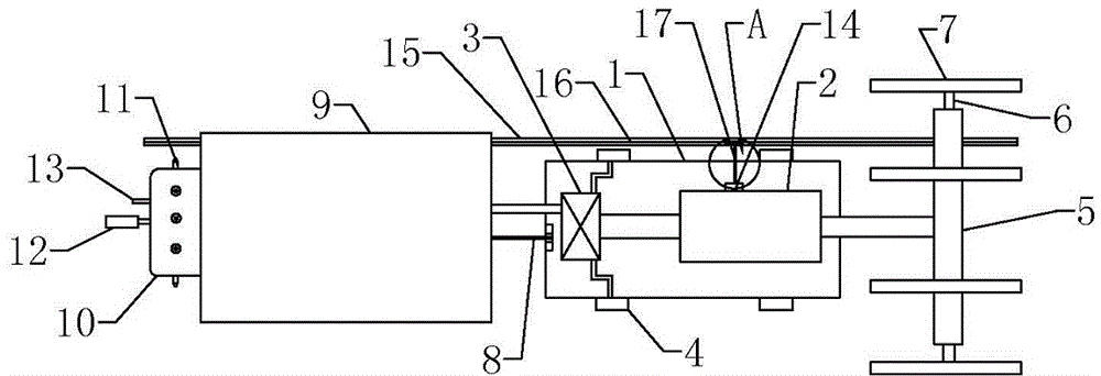
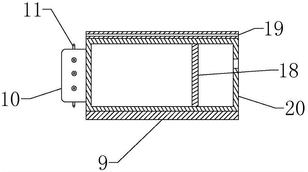
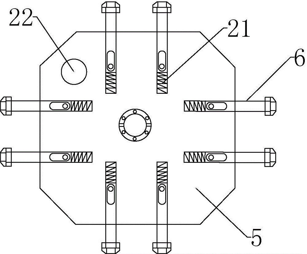
[0019] The reference signs in the drawings of the description include: base plate 1, double-axis motor 2, impeller shell 3, air bag wheel 4, fixed panel 5, tensioning shaft 6, derusting cutter head 7, hook 8, rust absorbing felt ring 9, Nozzle end cover 10, nozzle 11, heating plate 12, air pipe 13, junction box 14, power line 15, chute 16, pantograph 17, piston 18, channel hole 19, cylinder 20, tension spring 21, opening Hole 22.

[0020] Example basic reference Figure 1~Figure 4 Shown: the rust removal and painting device for the inner wall of the pipeline, including a biaxial motor 2, a junction box 14 for controlling the start and stop of the biaxial motor 2 is installed on the biaxial motor 2, there is a wiring port in the junction box 14, and the biaxial motor 2 is installed on On the base plate 1, the airbag wheel 4 is installed on the bottom of the base plate 1,...


PUM


Abstract

The invention discloses a rust removing and paint spraying device for the inner wall of a pipeline. The rust removing and paint spraying device comprises a bottom plate, rust removing equipment, power equipment and paint spraying equipment, wherein a connecting rod is connected between the rust removing equipment and the power equipment, and a hook is connected between the paint spraying equipment and the power equipment. The rust removing and paint spraying device is characterized in that the power equipment comprises an electricity transmission line and a driving mechanism, the driving mechanism is provided with an electricity inlet interface, and a pantograph is connected to the electricity inlet interface; the electricity transmission line is provided with an elastic insulating layer, a sliding groove is arranged in the insulating layer, and the pantograph is connected in the sliding groove in a sliding manner; an impeller shell is further arranged on the bottom plate, an impeller is arranged in the impeller shell in a rotating manner, and the impeller is driven by the driving mechanism to rotate; the driving mechanism is provided with a plurality of air bag wheels, and the air bag wheels communicate with the impeller shell; and the paint spraying equipment comprises a cylinder, a piston is arranged in the cylinder, one end of the cylinder is provided with a nozzle, and the other end of the cylinder communicates with the impeller shell. Compared with the prior art, the rust removing and paint spraying device has the advantages that the rust removing and paint spraying device can continuously work and uniformly spray a paint on the inner wall of the pipeline.

Description

technical field [0001] The invention relates to the field of rust removal and painting, in particular to pipeline rust removal and painting equipment. Background technique [0002] At present, for the rust removal and painting of the inner wall of long-distance and small-diameter pipelines on the market, PIG physical cleaning technology is mainly used. , It needs repeated processing for many times, which is time-consuming and labor-intensive, and the painting operation cannot be completed at the same time, and the work efficiency is low. [0003] In view of the above problems, the patent document with the application number CN201410008594.0 discloses a kind of automatic rust removal and painting equipment for the inner wall of the pipeline, which mainly includes three parts: the rust removal device, the power device, and the paint spraying device. The rotating front end of the universal coupling is connected with the fixed panel bolt, the rotating rear end of the universal ...

Claims


Application Information

Patent Timeline
Patent Type & Authority Applications(China)
IPC IPC(8): B24B27/033B24B41/04B24B47/12B24B55/06B05B13/06B05B9/047
CPCB05B9/047B05B13/06B24B27/033B24B41/04B24B47/12B24B55/06
Inventor 李庸健
Owner CHONGQING TENGTONG IND DESIGN
Why Eureka
Try Eureka