

Blade sharpening system and method of using the same
- Summary
- Abstract
- Description
- Claims
- Application Information
AI Technical Summary
Benefits of technology
Problems solved by technology
Method used
Image

Examples
first embodiment
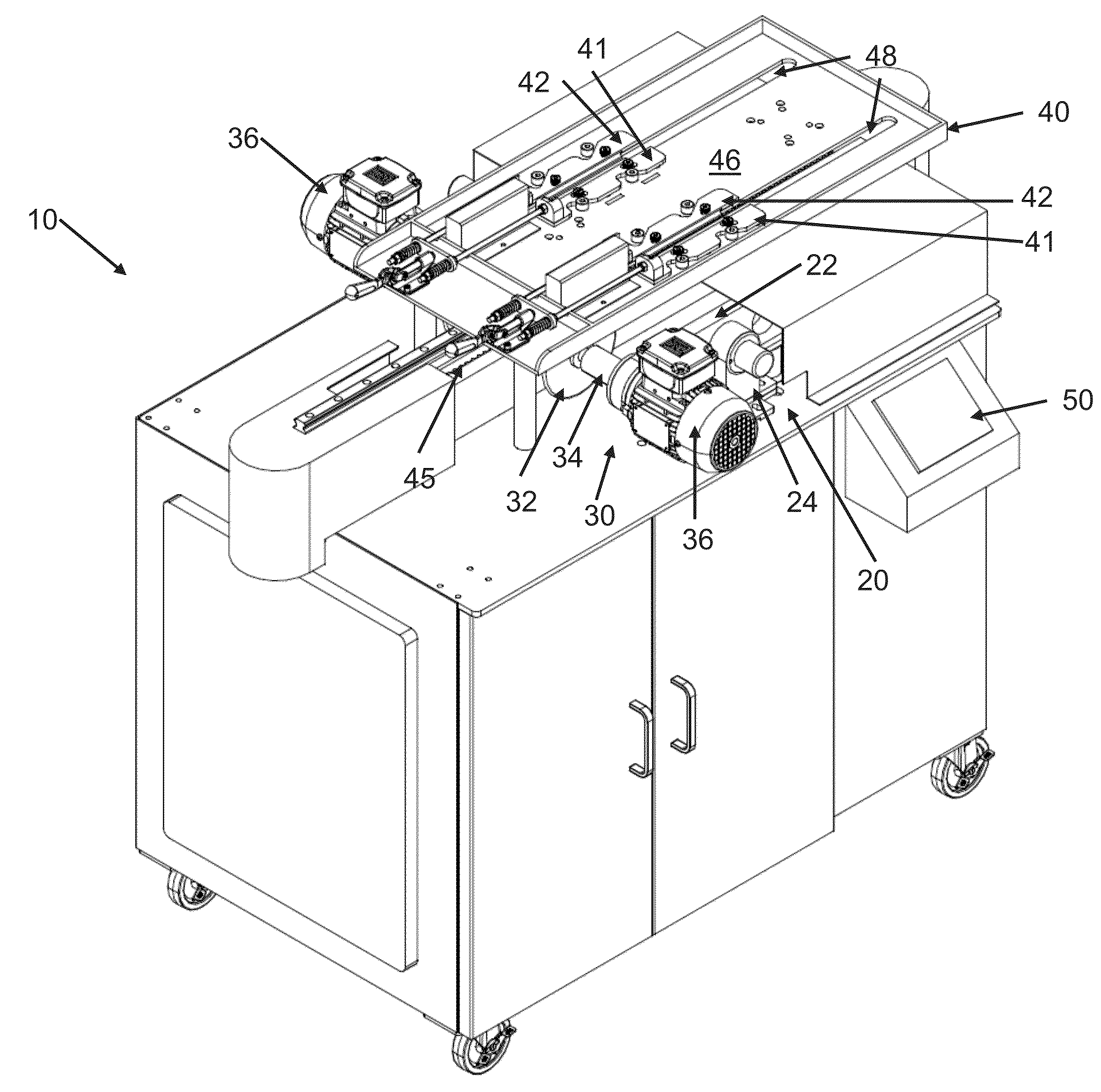
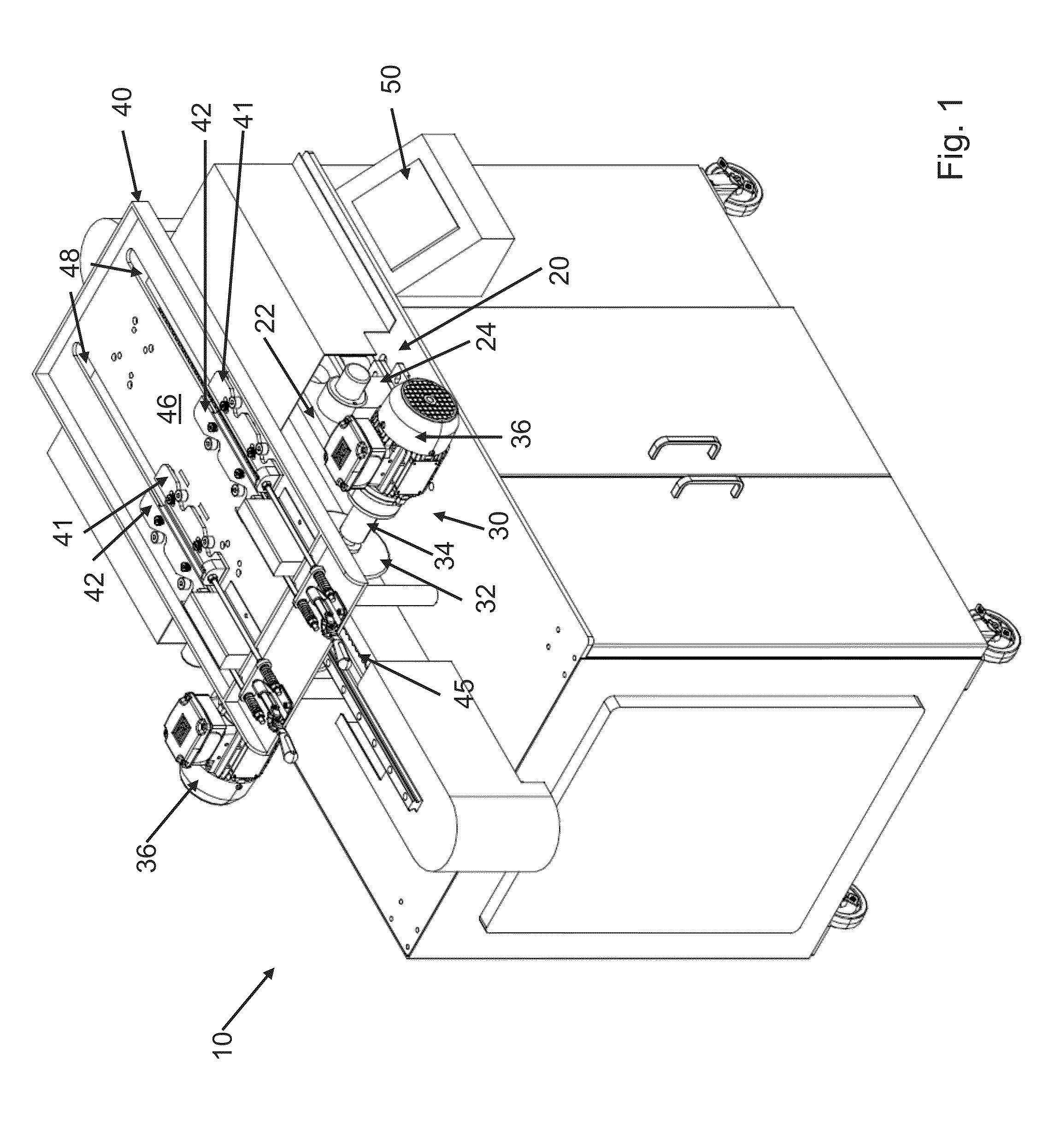
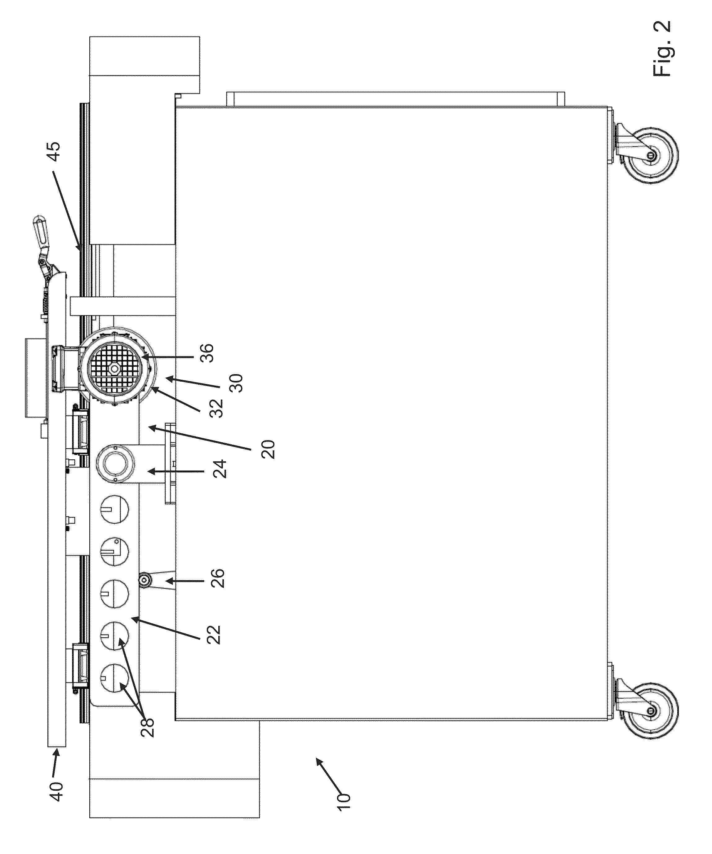
[0059]In a first embodiment there is disclosed a blade sharpening system comprising:[0060]a blade sharpening device 20 configured to contact said blade according to a predetermined shape of said blade comprising[0061]a grinding assembly 30 having a grinding wheel 32 demountably attached to a spindle 34 operatively coupled to a grinding wheel drive system 36, said grinding wheel configured to contact said blade with a constant grinding pressure and a constant grinding rotation speed;[0062]a blade holding apparatus 40 to slide said blade over said blade sharpening device 20, comprising[0063]parallel first and second gripping members 41, 42 for contacting opposite sides of said blade and align an edge of said blade with said grinding wheel 32 for sharpening; and[0064]a controller 50 operatively coupled to said blade sharpening device and said blade holding apparatus to control sharpening of said blade.
second embodiment
[0065]In a second embodiment, there is disclosed a method of sharpening blades with a blade sharpening system of the present invention, comprising the step of:
a) moving at least once said blade holding apparatus having a blade mounted thereon toward said grinding wheel in alignment with said blade, to contact said blade with said grinding wheel with a constant grinding pressure, and a constant grinding rotation speed, according to a predetermined shape of said blade, to sharpen and prevent deformation of said blade.
[0066]Referring now to the drawings, and more particularly to FIGS. 1 to 5, which illustrates a blade sharpening system 10 according to the present invention. The blade sharpening system 10 of the present invention may be used for sharpening at the same time one or more blades, and therefore, when the present invention is described as containing one element or part, it is within the purview of the person skilled in the art to adapt the disclosed subject matter to include ...
PUM
| Property | Measurement | Unit |
|---|---|---|
| Radius | aaaaa | aaaaa |
| Radius | aaaaa | aaaaa |
| Weight | aaaaa | aaaaa |
Abstract
Description
Claims
Application Information