Split-chamber pressure exchangers

a technology of pressure exchanger and split chamber, which is applied in the direction of positive displacement liquid engine, piston pump, machine/engine, etc., can solve the problems of fluid pressure, fluid pressure, and traditional pressure exchangers generally present another, so as to reduce the performance of pressure exchanger and complicate the system control electronics

Inactive Publication Date: 2010-01-21
PREXTOR SYST
View PDF5 Cites 30 Cited by
  • Summary
  • Abstract
  • Description
  • Claims
  • Application Information

AI Technical Summary

Benefits of technology

[0014]Furthermore, traditional pressure exchangers generally present another drawback, which is that the fluid to be pressurized (fluid 1) is forced to displace the fluid 2 once it has been depressurized. This is not so much of a problem in the case of desalinators because the water to be pressurized comes from the pre-treatment process, from whic...

Problems solved by technology

Although the system proposed in the previous section relating to desalination is fairly energetically efficient, it presents two problems:the outlet pressure of the reverse osmosis filters of the brine is always lower than that of the feed water, which means that it is necessary to install a booster pump increasing the pressure of the watersince the pre-treatment water and the brine are separated in the pressure-transmitting intermediate members, there is always a small though significant mixture of both fluids, therefore the pre-treatment water leaves the pressure exchangers with a higher salt concentration, which obviously jeopardizes the process
Furthermore, traditional pressure exchangers generally present another drawback,...

Method used


Image

  • Split-chamber pressure exchangers
  • Split-chamber pressure exchangers
  • Split-chamber pressure exchangers

Examples


Embodiment Construction

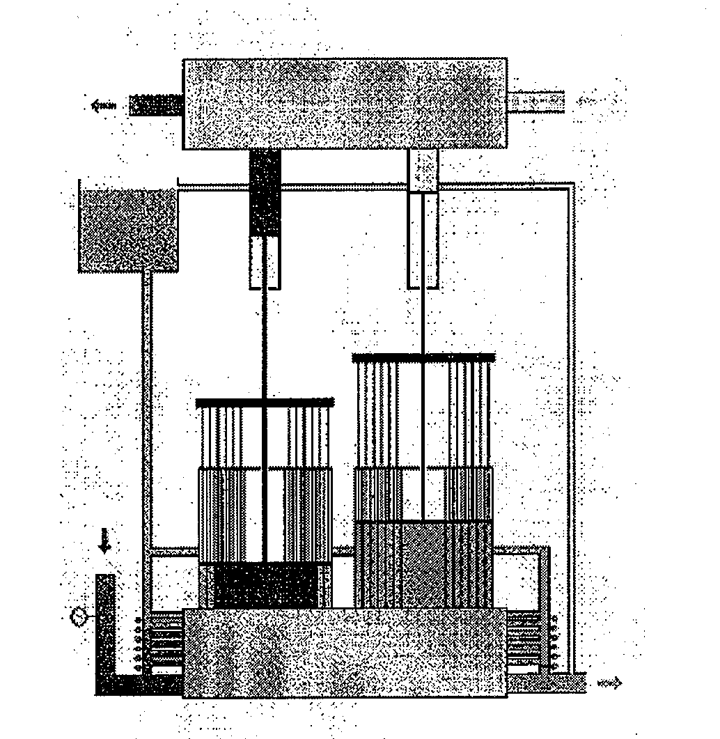
[0124]FIGS. 36 to 39 diagrammatically depict the operating process of a multistage SCPE, with seven concentric chambers located on the side of the pressurized feed fluid.

[0125]FIG. 36 shows the first of the lines starting to be filled and the second one starting to drain. The pressure gage at the inlet of the pressurized fluid records a high pressure of the fluid, therefore the valve feeding the concentric chambers closes and therefore only pressurized fluid enters the central cylinder. The valve system in the gray box in the figure allows the passage of pressurized fluid to the first line and prevents the passage thereof to the second line. Likewise, said system allows draining said already depressurized fluid from the second line. In addition, since the valve feeding the concentric chambers in the valve system shown in the figure in the second line is closed, it allows draining the fluid from the central cylinder but not from the remaining cylinders. The fluid contained in the rem...


PUM


Abstract

The invention relates to split-chamber pressure exchangers. Split-chamber pressure exchangers are characterized in that the pressure exchange chambers and the pistons thereof are split in two. Each fluid passes through the corresponding chamber thereof, such that said fluids cannot be mixed. The cross sections of the chambers can be varied in order to vary the transmitted pressure. The reverse line operation can be established and synchronized using a U-shaped tube with telescopic sides and a fixed base filled with fluid or diametrically opposed curved lines, and multiple arrangements can be used. Split-chamber pressure exchangers can be used as surface or well pumping systems and the pumping fluid used can differ from the fluid to be pumped. Different levels of any material can be exploited at any storage site using a chamber with elastic walls filled with fluid and attached to the bottom. Electric power can be generated by centrifuging the pre-pumped fluid.

Description

FIELD OF THE ART[0001]The invention is comprised within the field of pressure exchangers, which are for transmitting dynamic pressure from one fluid to another different fluid.[0002]Due to the innovations provided, the invention is transformed into a new pumping system for any type of fluids, and even into a new electric power generation system.STATE OF THE ARTPressure Exchangers[0003]Pressure exchangers were invented over more than twenty-five years ago and they basically consist of pressurizing one fluid (fluid 1 in FIG. 1) from the pressure of another fluid, which is depressurized after the process (fluid 2). There are several models, but they all basically work according to the diagram of FIG. 1. The fluid 1 is introduced in the interconnecting chambers by means of a system of shut-off and check valves, represented by the gray boxes. Once filled, the fluid 2 is allowed to pass through the other end, displacing said fluid by pushing an transmitting intermediate member which trans...

Claims


Application Information

Patent Timeline
IPC IPC(8): F04B9/10
CPCF04F13/00F04B9/1176
Inventor RUIZ DEL OLMO, FERNANDO
Owner PREXTOR SYST
Why Eureka
Try Eureka