F-theta lens, beam scanning device, and imaging apparatus

a beam scanning and f-theta technology, applied in the direction of lenses, instruments, optical elements, etc., can solve the problems of wasting material, requiring labor-intensive cutting of spherical lenses into strips, and high material cos

Inactive Publication Date: 2002-03-14
FUJIFILM CORP +1
View PDF2 Cites 25 Cited by
  • Summary
  • Abstract
  • Description
  • Claims
  • Application Information

AI Technical Summary

Benefits of technology

[0011] The f-.theta. lens of the present invention uses a cylindrical lens having a curvature only in the deflecting direction of the light beams. Such a cylindrical lens may be manufactured by forming a primary cylindrical lens whose cylindrical surface has a pretty large length in a perpendicular direction to the direction of curvature, and then cutting the primary cylindrical lens along the direction of curvature into a number of lens pieces of a constant width or height. Every one of subsequent cut pieces is usable as a component of the f-.theta. lens, so any waste is not produced from the primary cylindrical lens. Therefore, the cylindrical lenses used in the f-.theta. lens of the present invention may be manufactured at a low cost, so the manufacture cost of the f-.theta. lens of the present invention is low in comparison with the conventional f-.theta. lens using those lens elements which are manufactured by cutting round lenses into strips. It is to be noted that cutting process of the primary cylindrical lens may be done at any stage of manufacturing the individual lens elements, e.g. before finishing the surface of the primary cylindrical lens.
[0013] This configuration is effective to prevent curvature of the field of the f-.theta. lens from being worsened, and maintain good speed f-.theta. characteristics. It is to be noted that the speed f-.theta. characteristics indicate the proportionality of the scanning speed of the light beams on the scanning plane to the angular speed of deflection. That is, with good f-.theta. characteristics, the scanning speed of the light beams is maintained constant through the entire scanning length.
[0014] According to another preferred embodiment, at least one of the three lens elements is inclined about a parallel axis to the deflecting direction. This configuration is effective to prevent interference caused by multiple reflection of light beams between the lens surfaces. Especially by inclining the first lens element, those light beams multiple-reflected between the optical deflection device and the first lens element are prevented from being projected toward the scanning plane, so the ghosts are effectively prevented.
[0015] According to a further embodiment, the first and second lens elements are cemented to each other. This configuration reduces the risk of deviation of the lens elements from their proper positions.
[0022] The color imaging apparatus of the present invention shifts the output timings of the light beams of different wavelengths so that the scanning start position of these light beams on the scanning plane will coincide with each other. That is, chromatic aberrations of the f-.theta. lens are compensated a certain degree by shifting the output timings of the light beams. Therefore, the f-.theta. lens is not required to correct the chromatic aberrations entirely by itself. So the f-.theta. lens may be manufactured at a low cost, using inexpensive lens elements that may be produced at a high efficiency from inexpensive glass materials, without lowering the lens performance or the image quality.

Problems solved by technology

However, cutting the spherical lens into a strip requires is labor-consuming, because it is necessary to locate the cutting positions very strictly.
In addition, since the peripheral portions of the spherical lens are thrown way uselessly, it is a waste of material, and the material cost are pretty large.
But it is still a waste of lens material, as there remain unused portions in those spherical lenses.
Moreover, as compared to the strip-shaped spherical lenses, the whole ones obviously require a larger space, and thus enlarges the apparatus size.
In that case, recorded images will suffer color failures.
For better correction, however, the sorts of glass materials for the f-.theta. lens are limited to expensive ones, and also the number of lens elements must be increased.
Thus, the f-.theta. lens becomes expensive.
Indeed Japanese Laid-open Patent Application No. 6-18803 discloses an f-.theta. lens using a cylindrical lens as one component, but the other component of this prior art is a spherical lens, so it needs a relatively high manufacture cost.
Although there has been disclosed an f-.theta. lens system whose components are all cylindrical lenses in Japanese Laid-open Patent Application No. 3-130717, the f-.theta. lens of this prior art has a problem that sufficient lens performance cannot always be achieved because of tolerance in manufacture.
However, this solution results in rising the manufacture cost.

Method used


Image

  • F-theta lens, beam scanning device, and imaging apparatus
  • F-theta lens, beam scanning device, and imaging apparatus
  • F-theta lens, beam scanning device, and imaging apparatus

Examples


first embodiment

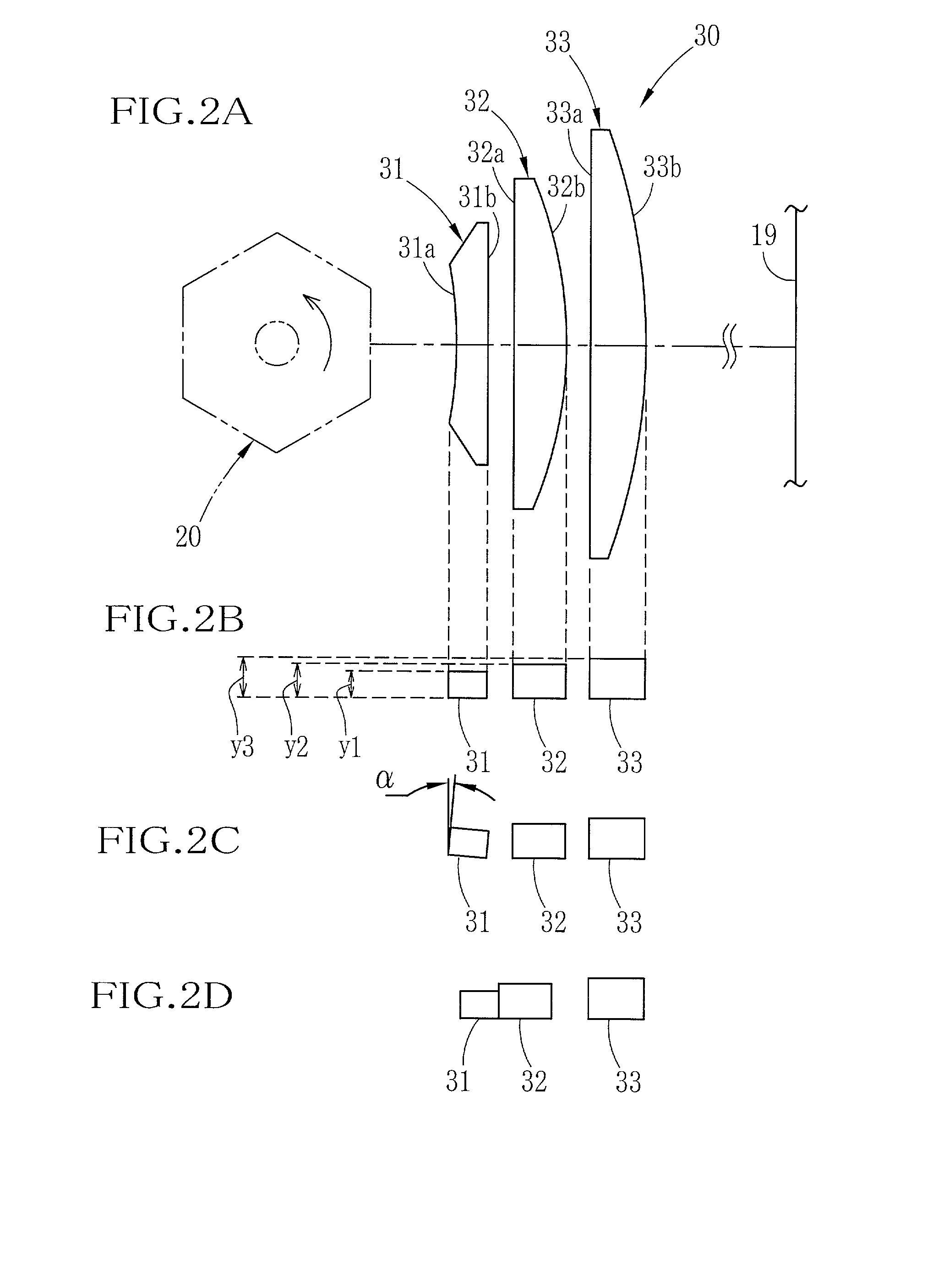
[0077] It is also possible to cement the first and second lens elements 31 and 32 to each other as a doublet, as shown in FIG. 2D. This configuration provides the same effect as the first embodiment shown in FIG. 2B, and also reduces the risk of deviation of the lens elements from their proper positions. Such a deviation would damage the lens performance.

example 1

[0078] In Example 1, the frequencies fm, fc and fy of the clock pulses generated from the oscillators 51M, 51C and 51Y are respectively determined as follows:

[0079] fm:fc:fy=1 / 1.000459:1:1 / 0.999620

[0080] The f-.theta. lens 30 is composed of first to third lens elements having the same configuration as the embodiment shown in FIG. 2A, and the first and second lens elements 31 and 32 are cemented to each other to form a doublet, as shown in FIG. 2D.

[0081] Numerical values for Example 1 are as set forth below.

[0082] .vertline.f.vertline.=373.324 mm

[0083] .vertline.f1.vertline.=153.955 mm

[0084] .vertline.f23.vertline.=98.170 mm

[0085] .theta.=50.degree.

[0086] wherein f represents the total focal length of the f-.theta. lens 30, f1 represents the focal length of the first lens element 31, f23 represents a composite focal length of the second and third lens elements, .theta. represents the deflection angle of the light beams by the polygonal mirror 20.

[0087] Table 1 shows lens data of Exam...

example 2

[0092] In the Example 2, the frequencies fm, fc and fy of the clock pulses generated from the oscillators 51M, 51C and 51Y are respectively determined as follows:

[0093] fm:fc:fy=1 / 1.000582:1:1 / 0.999532

[0094] The f-.theta. lens 30 is composed of first to third lens elements having the same configuration as the embodiment shown in FIG. 2A, and the first to third lens elements 31 to 33 are arranged separately from each other in a manner as shown in FIG. 2B.

[0095] Numerical values for Example 2 are as set forth below, and Table 2 shows lens data of Example 2.

[0096] .vertline.f.vertline.=276.541 mm

[0097] .vertline.f1.vertline.=112.901 mm

[0098] .vertline.f23.vertline.=93.597 mm

[0099] .theta.=67.degree.

2TABLE 2 i R D N .nu. DEFLECTION 16.0 POINT 1 -80.600 5.9 1.72825 28.32 2 .infin. 4.1 3 .infin. 10.0 1.51680 64.20 4 -77.750 4.5 5 .infin. 10.5 1.51680 64.20 6 -115.400 326.057 IMAGE PLANE

[0100] As shown in Table 2, the refractive indexes N1, N2 and N3 of the first to third lens elements 31 ...


PUM


Abstract

An f-theta lens is composed of a negative lens element of a negative power, and second and third lens elements of a positive power, arranged in this order from the side of a optical deflection device, wherein at least one surface of the lens elements is a cylindrical surface that has a refractive power only in the deflecting direction. The f-theta lens satisfies the conditions: N1>N2=N3, υ1<υ2=υ3, and 4<=|f23 / f1.D0|<=16, wherein N1, N2 and N3 represent refractive indexes, υ1, υ2 and υ3 Abbe constants of the first to third lens elements respectively, f1 the focal length of the first lens element, f23 the composite focal length of the second and third lens elements, and D0 a distance from the optical deflection device to the lens surface of the first lens element.

Description

BACKGROUND ARTS[0001] The present invention relates to an f-.theta. lens that focuses light beams on a plane and scans the light beams across the scanning plane at substantially constant speed. The present invention relates also to an beam scanning device using the f-.theta. lens and a color imaging apparatus using the beam scanning device.[0002] The beam scanning device is provided with a light source generating light beams, and an optical deflection device, like a polygonal mirror, that deflects the light beams in a constant direction. The deflected light beams are projected onto a plane through the f-.theta. lens, to sweep or scan the plane in a constant direction. The f-.theta. lens is a lens that has a property to make the light beams move on the scanning plane proportionally to a deflection angle .theta. of the optical deflection device. In the beam scanning device, the f-.theta. lens is used for making the scanning speed of the light beams on the scanning plane proportional t...

Claims


Application Information

Patent Timeline
Patent Type & Authority Applications(United States)
IPC IPC(8): G02B3/06B41J2/44G02B13/00G02B13/18G02B26/10G02B26/12H04N1/04H04N1/113H04N1/23
CPCG02B13/0005
Inventor KODAMA, KENICHI
Owner FUJIFILM CORP
Why Eureka
Try Eureka