Coding apparatus, coding method, program for executing the method, and recording medium storing the program

a coding apparatus and a technology for coding methods, applied in the field of coding apparatuses, can solve the problems of increasing the scale of circuitry involved, the computational intensiveness of avc coding methods for coding and decoding, and the increase of processing conducted by arithmetic coders b>3/b>, so as to reduce the scale of circuitry involved, the effect of reducing the energy consumed thereby and speed

Inactive Publication Date: 2010-03-30
SONY CORP
View PDF6 Cites 27 Cited by
  • Summary
  • Abstract
  • Description
  • Claims
  • Application Information

AI Technical Summary

Benefits of technology

[0027]As a result of the configurations in accordance with the embodiments described above, the number of generated bits can be predicted within a fixed range before performing binary arithmetic coding. Consequently, binary arithmetic coding can be performed at lower speeds compared to the case wherein the bit rate is controlled according to the number of bits in the coded data after performing binary arithmetic coding. As a result, rate control can be performed at sufficiently high speeds even if the portions of the configuration related to binary arithmetic coding are simplified such that the scale of circuitry involved therein and the energy consumed thereby are reduced. Thus, in the present invention, the portions of the configuration related to arithmetic coding are simplified compared to that of the related art, such that the scale of circuitry involved therein and the energy consumed thereby are reduced.

Problems solved by technology

Among such coding methods, the AVC coding method is more computationally intensive for coding and decoding than the MPEG-2 and MPEG-4 coding methods.
However, the processing conducted by the arithmetic coder 3 is very computationally intensive.
Consequently, there is a problem in that if a coding apparatus 1 in accordance with the related art is to code the input picture data D1 in real-time, then the scale of circuitry involved is increased due to the increased complexity in the configuration of the arithmetic coder 3, and furthermore energy consumption is also increased.

Method used


Image

  • Coding apparatus, coding method, program for executing the method, and recording medium storing the program
  • Coding apparatus, coding method, program for executing the method, and recording medium storing the program
  • Coding apparatus, coding method, program for executing the method, and recording medium storing the program

Examples


first embodiment

[0039](1) Configuration of the Embodiment

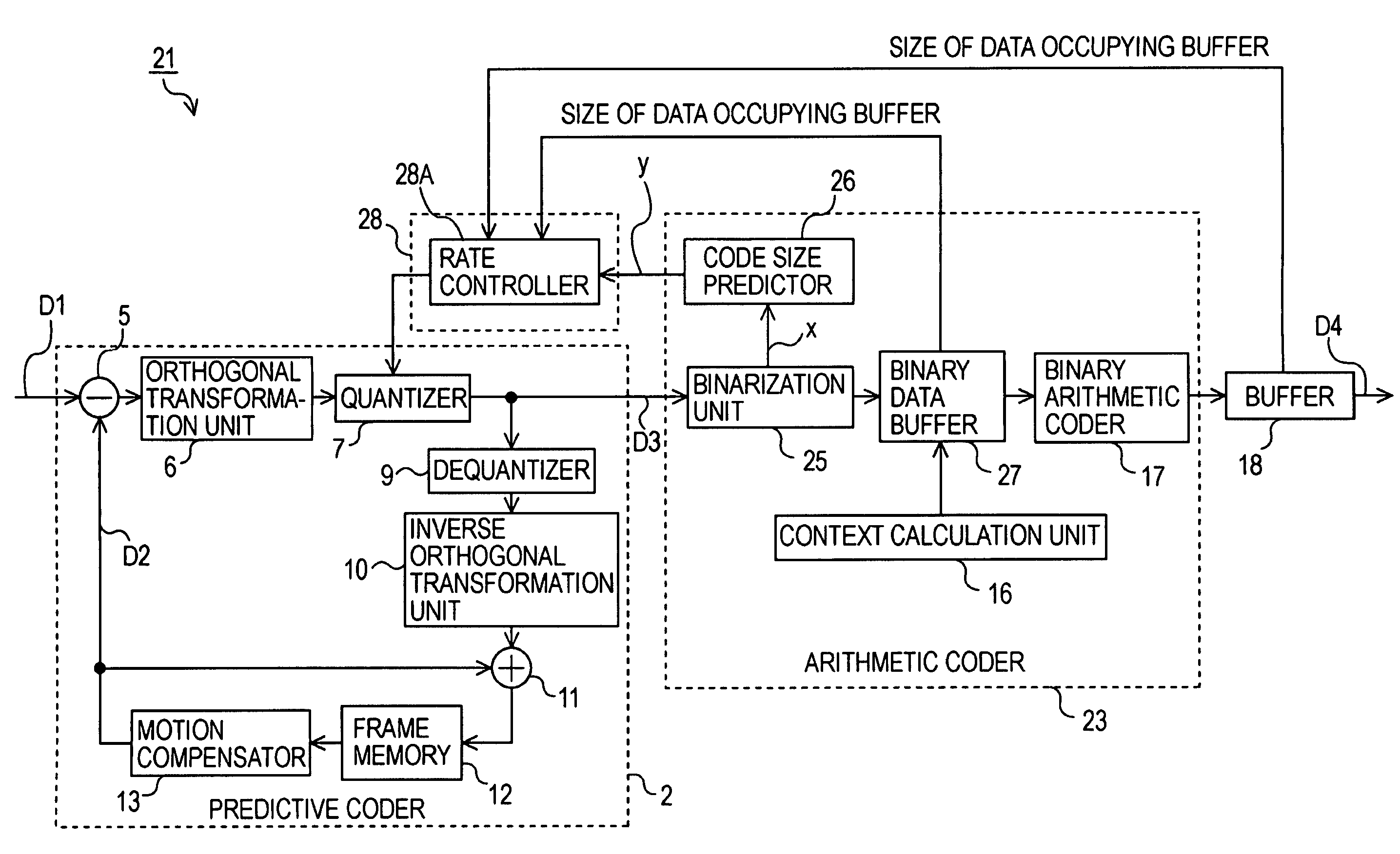
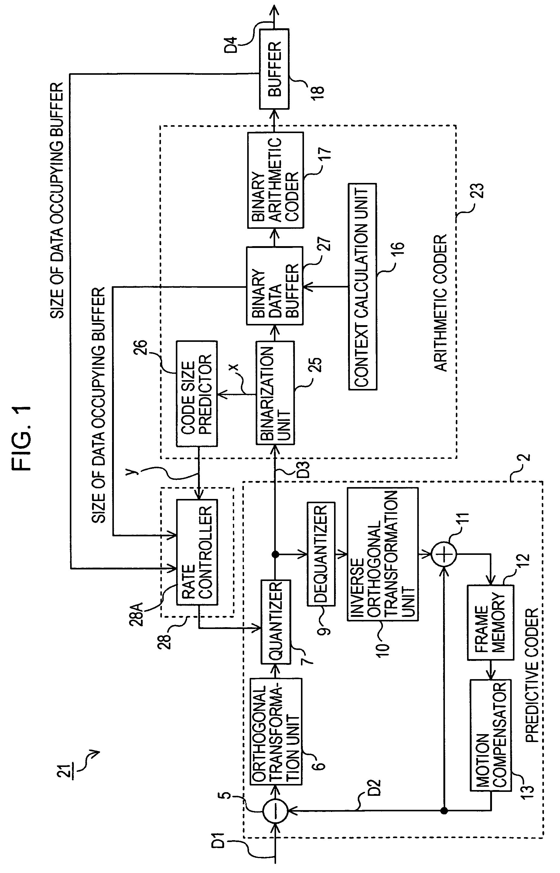
[0040]FIG. 1 is a block diagram illustrating the configuration of a coding apparatus in accordance with a first embodiment of the present invention. The coding apparatus 21 depicted in FIG. 1 is configured identically to the coding apparatus 1 previously described with reference to FIG. 9, except in that an arithmetic coder 23 and a controller 28 have been provided in place of the arithmetic coder 3 and the controller 8, respectively. Furthermore, the arithmetic coder 23 is configured identically to the arithmetic coder 3 of the coding apparatus 1 previously described with reference to FIG. 9, except in that a binarization unit 25, a code length predictor 26, and a binary data buffer 27 have been provided in place of the binarization unit 15.

[0041]In the arithmetic coder 23, the binarization unit 25 operates similarly to the binarization unit 15, converting the many-valued syntax elements from the output data of the quantizer 7, motion vector...

second embodiment

[0088]FIG. 6 is a block diagram illustrating, by way of comparison with FIG. 5, the configuration of a coding apparatus in accordance with a second embodiment of the present invention. The coding apparatus 31 illustrated in FIG. 6 is provided with a controller 38 in place of the controller 28. The controller 38 herein is configured identically to the controller 28 in accordance with foregoing embodiment, except in that a rate controller 38A has been provided in place of the rate controller 28A.

[0089]Using the rate controller 38A, the controller 38 in accordance with the present embodiment dynamically varies the predictive function according to the level of activity detected by the activity detector. The rate controller 38A is configured identically to the rate controller 28A, except in that the rate controller 38A is also configured to dynamically vary the predictive function according to the level of activity as described above.

[0090]More specifically, when the level of activity ex...

third embodiment

[0093]FIG. 7 is a block diagram illustrating, by way of comparison with FIG. 5, the configuration of a coding apparatus in accordance with a third embodiment of the present invention. The coding apparatus 41 illustrated in FIG. 7 is provided with a controller 48 in place of the controller 28. The controller 48 herein is configured identically to the controller 28 in accordance with the embodiment described previously, except in that a rate controller 48A has been provided in place of the rate controller 28A.

[0094]Using the rate controller 48A, the controller 48 in accordance with the present embodiment dynamically varies the predictive function according to the values in the output data output from the quantizer 7. The rate controller 48A is configured identically to the rate controller 28A, except in that the rate controller 48A is also configured to dynamically vary the predictive function according to the values in the output data output from the quantizer 7 as described above.

[0...


PUM


Abstract

A coding apparatus that codes video data using an arithmetic coding scheme such as the AVC standard includes an orthogonal transformation unit, a quantizer, an arithmetic coder, and a controller. The arithmetic coder includes a binarization unit, a binary arithmetic coder, and a code length predictor. The code length predictor outputs a predicted number of bits by evaluating a predictive function using, as the argument of the function, the bin size of the binary symbols generated from input data during coding. The controller controls the coding bit rate by changing the quantization scale of the quantizer on the basis of the predicted number of bits. The predictive function is defined such that the predicted number of bits increases as the bin size increases, and furthermore such that the polynomial degree of the function changes when the bin size exceeds a predefined threshold value.

Description

CROSS REFERENCES TO RELATED APPLICATIONS[0001]The present invention contains subject matter related to Japanese Patent Application JP 2007-220596 filed in the Japanese Patent Office on Aug. 28, 2007, the entire contents of which are incorporated herein by reference.BACKGROUND OF THE INVENTION[0002]1. Field of the Invention[0003]The present invention relates to a coding apparatus, a coding method, a program for executing the method, and a recording medium storing the program, the above being applicable for use in the coding of video data by means of the H.264 ISO / IEC 14496-10 AVC coding method (hereinafter referred to as AVC). More particularly, the present invention relates to configurations for arithmetic coding processing wherein the bit rate is controlled by predicting the number of generated bits from the bin size, such prediction being conducted with the use of a predictive function whose polynomial degree changes once the bin size exceeds a threshold value. The configurations ...

Claims


Application Information

Patent Timeline
Patent Type & Authority Patents(United States)
IPC IPC(8): H03M7/00H04N19/60H03M7/40H04N19/115H04N19/126H04N19/14H04N19/146H04N19/147H04N19/157H04N19/176H04N19/196H04N19/503H04N19/51H04N19/593H04N19/61H04N19/91
CPCH03M7/40H03M7/4006H04N19/172H04N19/149H04N19/152H04N19/107H04N19/124H04N19/14H04N19/61H04N19/91
Inventor KOO, SUNG-YUL
Owner SONY CORP
Why Eureka
Try Eureka