Arrangements for energy conditioning

a technology of energy conditioning and arrangement, applied in the direction of emergency protective arrangement for limiting excess voltage/current, overvoltage protection resistor, etc., can solve the problem of limiting the performance of electronic circuitry, exacerbate the noise problem, propagating energy utilizing prior art passive devices may experience increased levels of energy parasitic interferen

Inactive Publication Date: 2010-03-30
X2Y ATTENUATORS L L C
View PDF621 Cites 19 Cited by
  • Summary
  • Abstract
  • Description
  • Claims
  • Application Information

AI Technical Summary

Problems solved by technology

Today, as the density of electronics within applications increases, unwanted noise byproducts of the increased density may limit the performance electronic circuitry.
This antenna-analogous performance may exacerbate the noise problem in that, at higher frequencies, propagating energy utilizing prior art passive devices may experience increased levels of energy parasitic interference, such as various capacitive and / or inductive parasitics.
These increases may be due, in part, to the combination of constraints resulting from functionally or structurally limitations of prior art solutions, coupled with the inherent manufacturing or design imbalances and performance deficiencies of the prior art.

Method used


Image

  • Arrangements for energy conditioning
  • Arrangements for energy conditioning
  • Arrangements for energy conditioning

Examples


Embodiment Construction

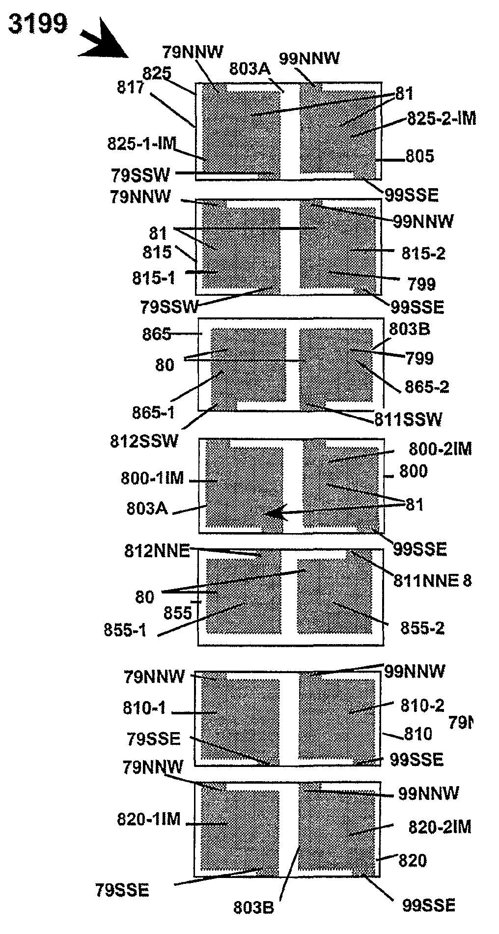
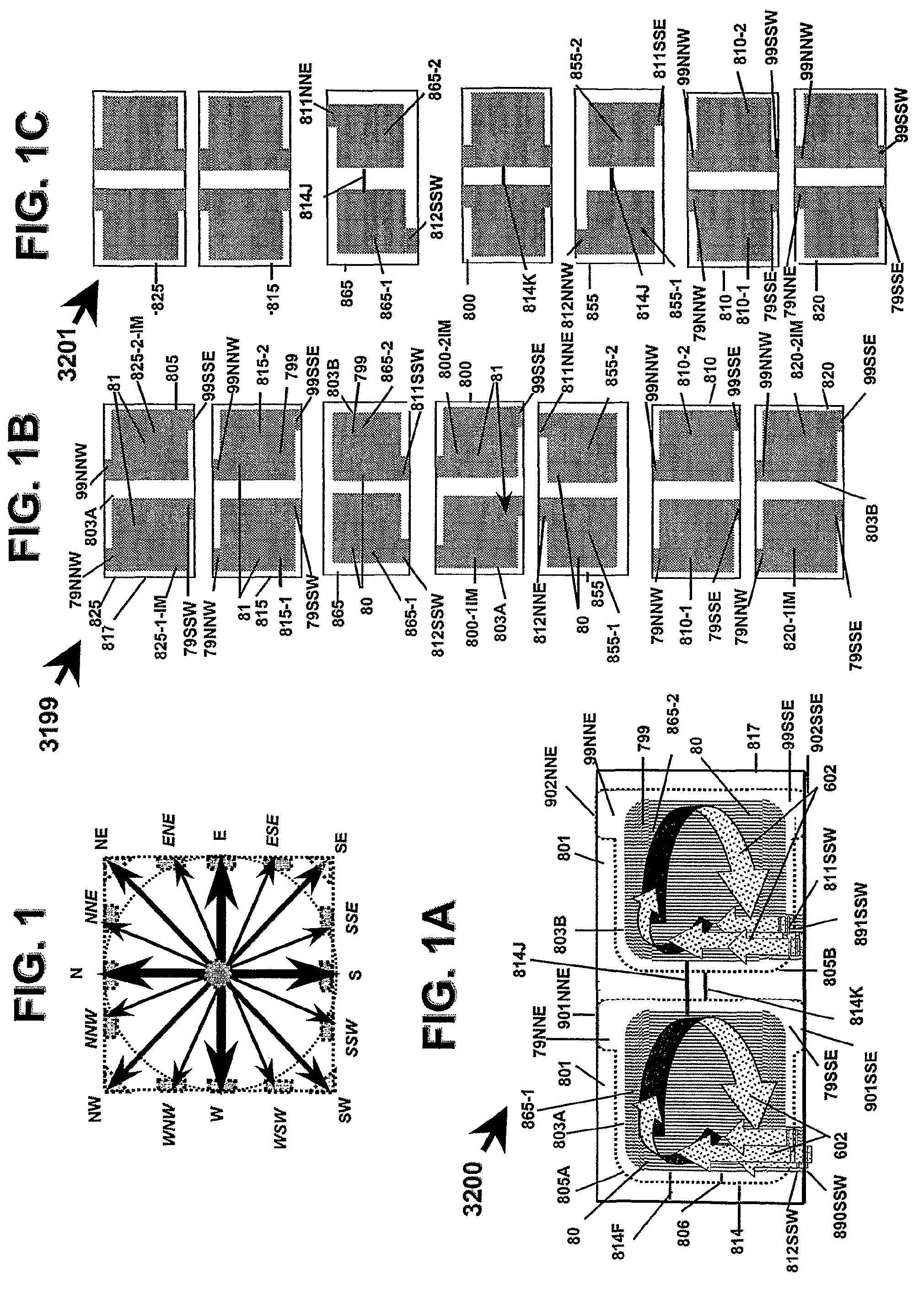
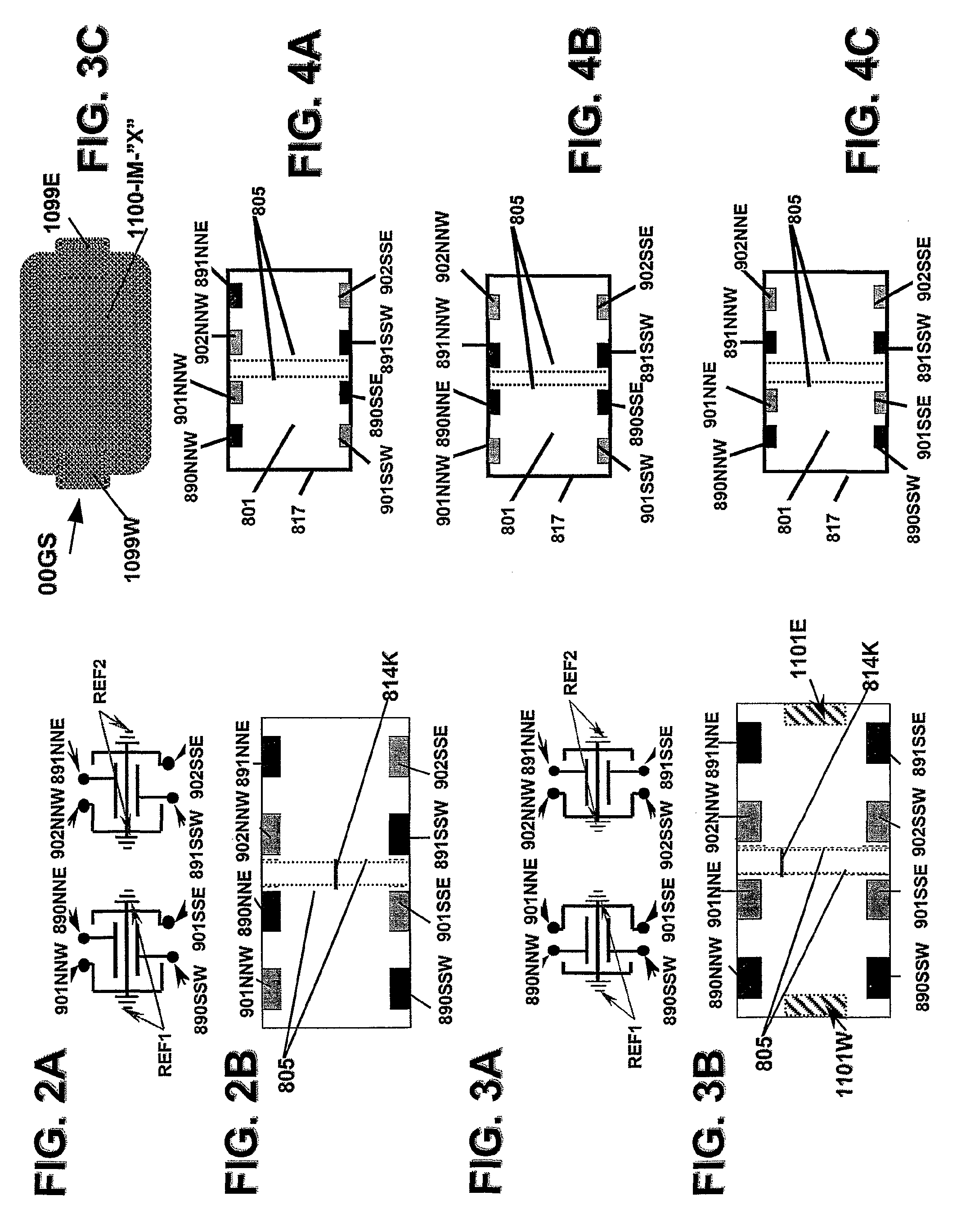
[0043]It is to be understood that the figures and descriptions of the present invention have been simplified to illustrate elements that are relevant for a clear understanding of the present invention, while eliminating, for the purpose of clarity, many other elements found in typical energy conditioning systems and methods. Those of ordinary skill in the art will recognize that other elements and / or steps are desirable and / or required in implementing the present invention. However, because such elements and steps are well known in the art, and because they do not facilitate a better understanding of the present invention, a discussion of such elements and steps is not provided herein. The disclosure herein is directed to all such variations and modifications to such elements and methods known to those skilled in the art.

[0044]Additionally, it will be apparent to those skilled in the art that terms used herein that may include a whole, or a portion of a whole, such as “energy”, “sys...


PUM

PropertyMeasurementUnit
thicknessaaaaaaaaaa
energy pathwayaaaaaaaaaa
conductiveaaaaaaaaaa

Abstract

Circuit arrangement embodiments that use relative groupings of energy pathways that include shielding circuit arrangements that can sustain and condition electrically complementary energy confluences.

Description

CROSS REFERENCE TO RELATED APPLICATIONS[0001]This application is a continuation of application Ser. No. 10 / 479,506, filed Dec. 10, 2003, now issued as U.S. Pat. No. 7,336,468, which is a U.S. National Stage Application of International Application PCT / US02 / 21238, filed Jul. 2, 2002, which is a continuation-in-part of application Ser. No. 10 / 023,467, filed Dec. 17, 2001, now abandoned, which is a continuation-in-part of application Ser. No. 09 / 996,355, filed Nov. 29, 2001, now abandoned, which is a continuation-in-part of application Ser. No. 10 / 003,711, filed Nov. 15, 2001, now abandoned, which is a continuation-in-part of application Ser. No. 09 / 982,553, filed Oct. 17, 2001, now abandoned;[0002]and this application is a continuation of application Ser. No. 10 / 479,506, filed Dec. 10, 2003, now issued as U.S. Pat. No. 7,336,468, which is a continuation-in-part of application Ser. No. 10 / 115,159, filed Apr. 2, 2002, now issued as U.S. Pat. No. 6,894,884, which is a continuation-in-par...

Claims


Application Information

Patent Timeline
Patent Type & Authority Patents(United States)
IPC IPC(8): H02H9/00H02H9/06H05K9/00
CPCH01L23/50H05K9/00H05K9/0071H01L23/552Y10T29/49124H01L2924/3011H01L2924/0002H01L2924/3025Y10T29/49117Y10T29/49194H01L2924/00
Inventor ANTHONY, ANTHONY A.ANTHONY, WILLIAM M.
Owner X2Y ATTENUATORS L L C
Why Eureka
Try Eureka