Support structure torque transfer function

a technology of supporting structure and torque transfer, which is applied in the direction of machine supports, instruments, casings/cabinets/drawers of electrical appliances, etc., can solve the problems of limited style design of the entire supporting structure, dullness, and inability to provide flat panel displays in height and along the forward/backward direction, etc., to achieve the effect of restricting the style design of the supporting structur

Inactive Publication Date: 2010-04-06
JARLLYTEC CO LTD
View PDF7 Cites 34 Cited by
  • Summary
  • Abstract
  • Description
  • Claims
  • Application Information

AI Technical Summary

Benefits of technology

[0007]In view of the foregoing shortcomings of the prior art, the inventor of the present invention based on years of experience in the related industry hopes to overcome the drawback that the aforementioned resilient support, torsion spring for example, of the support structure can only be disposed between the base hinge and the connection device, thereby seriously restricting the style design of the support structure. It is hoped that the change in torque resulted from the tilting adjustment of the connection device can be transferred to the resilient support part disposed elsewhere through a torque transfer device. Such a design can realize the diverse styles of the support structure and thus meet consumers' demands. After numerous experiments and tests, “support structure provided with a torque transfer function” according to the present invention has been achieved.

Problems solved by technology

However, this practice cannot provide flat panel displays in height and along forward / backward direction.
Since the torsion spring has long been disposed between the base hinge and the connection device, the style design of the entire support structure is limited and dull. if the torsion spring can be moved to other place of the support structure, a torque transfer mechanism is required for the torsion spring and the base hinge, which demands urgent attention.

Method used


Image

  • Support structure torque transfer function
  • Support structure torque transfer function
  • Support structure torque transfer function

Examples


Embodiment Construction

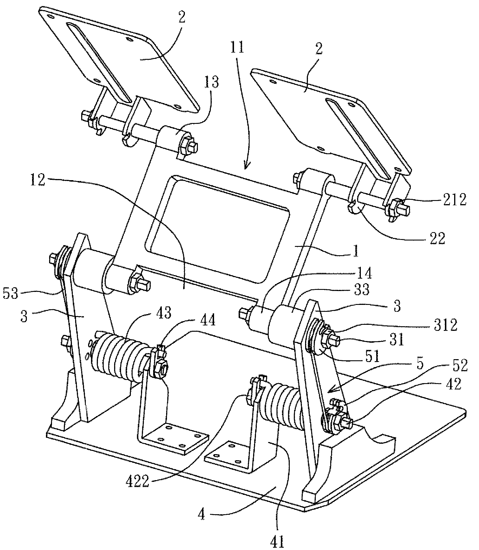
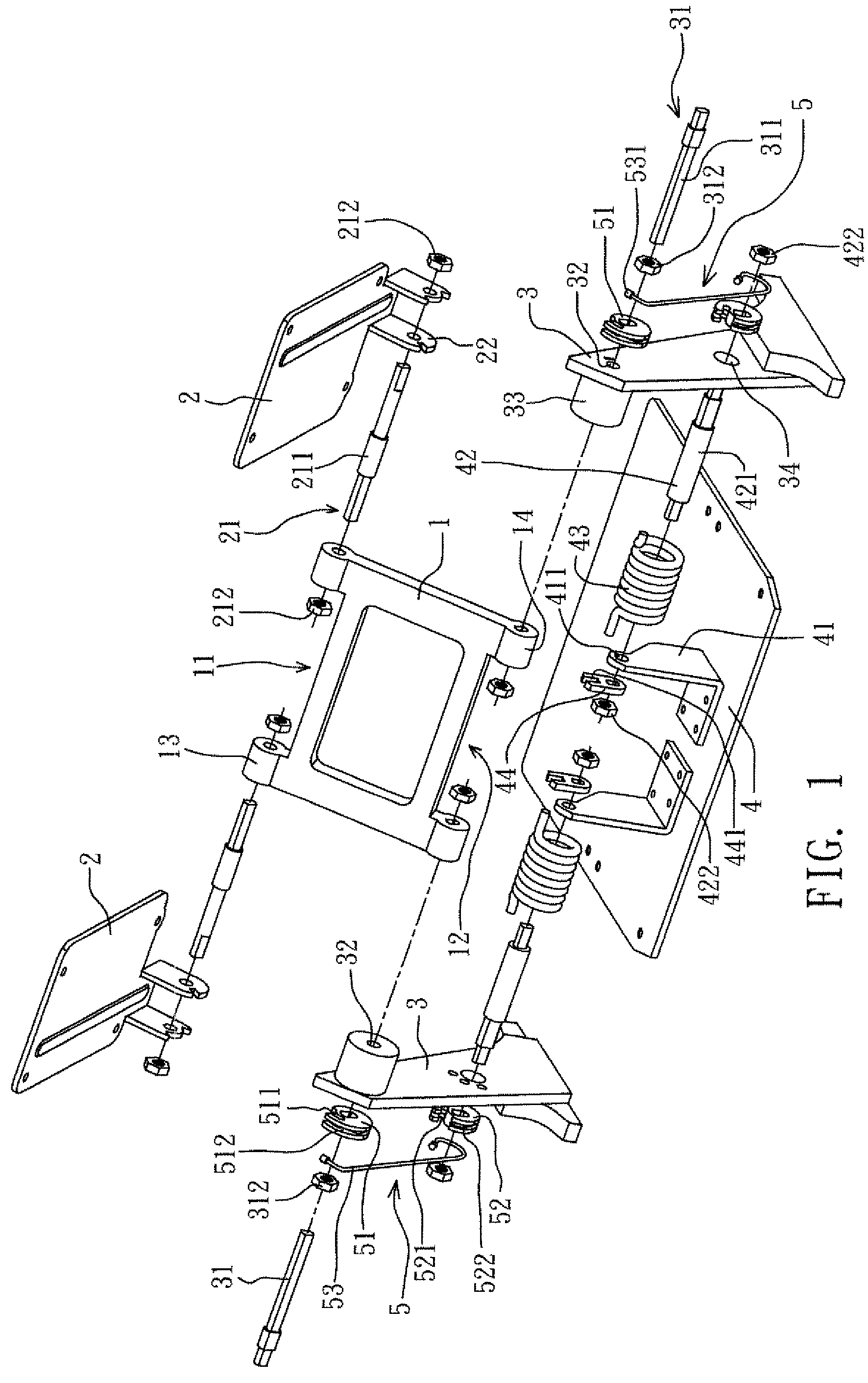
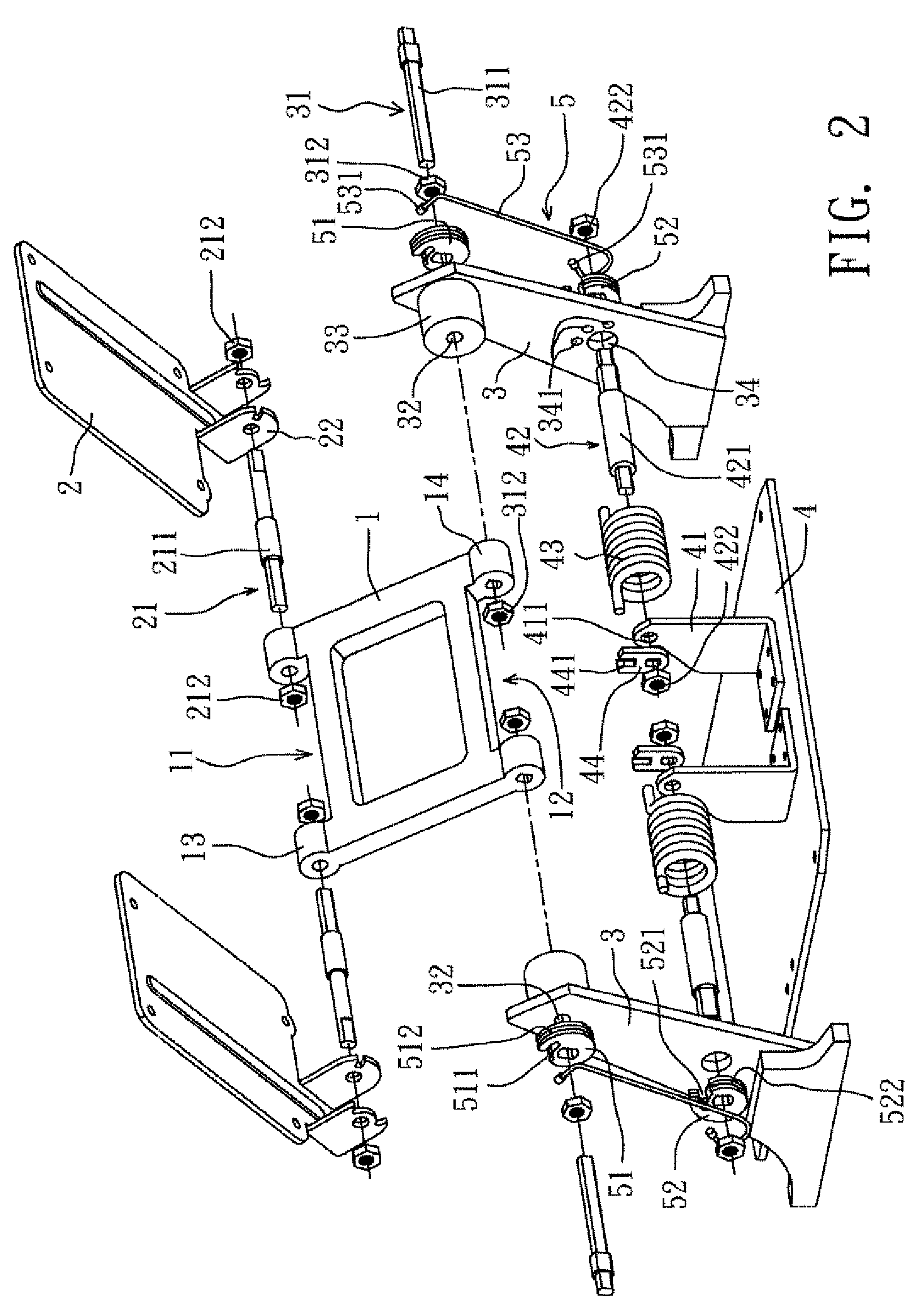
[0025]With reference to FIGS. 1 and 2, a support structure according to the present invention comprises a link member 1, a support 2, a pair of main brackets 3, a base member 4, and a torque transfer device 5.

[0026]The link member 1 is plate body, whose top and bottom have an upper end 11 and a lower end 12, respectively, such that a support hinge 21 and an intermediate hinge 31 are pivoted to a support 2 and a pair of main brackets 3, thereby achieving a rotatable condition. As shown in the aforementioned figures, the upper end 11 and lower end 12 extend to form a pair of upper hinge supporting part 13 and a pair of lower hinge supporting parts 14, respectively.

[0027]The support 2 is pivoted to the upper end 11 of the link member 1 through the support hinge 21 so as to render the support 2 rotatable with respect to the link member 1. The support hinge 21 is pivoted to the upper hinge supporting parts 13 on the upper end 11 of the link member 1 through two upper pivots 211, such tha...


PUM


Abstract

The invention provides a support structure with torque transfer function including a link member having an upper end and a lower end; a pair of main brackets located on a surface of a base member and being pivotally connected to the lower end of the link member through an intermediate hinge. The link member is rotatably pivoted between the two main brackets. The base member has a pair of auxiliary brackets located at one side of the pair of main brackets. A base hinge is socketingly connected to a resilient support and disposed between the main brackets and the auxiliary brackets. A torque transfer device having upper and lower rotation parts pivoted to the intermediate hinge and the base hinge so as to move synchronously together and a connecting part linking the upper and lower rotation parts to rotate in the same direction, thereby forming a torque transmission path.

Description

FIELD OF THE INVENTION[0001]The present invention relates to a support structure, and more particularly, to a support structure with torque transfer function.BACKGROUND OF THE INVENTION[0002]The support structure is to connect with a supporter, a platform for example, on which objects, notebook computer for example, can be rested. As a result, the support structure is said to have a receiving function. The platform on the top is usually capable of being adjusted in height with respect to the base on the bottom. When in use, the height between the platform and the base is adjusted appropriately to meet users' demand, whereas, when not in use, the platform is lowered to the lowest position to save space.[0003]Recently flat panel displays, such as liquid crystal display (LCD) monitors, LCD TVs, or plasma TVs, have the advantages of lightweight, thinness, and radiation-free and thus have gradually replaced conventional cathode ray tube (CRT) monitors. Consequently, a support structure h...

Claims


Application Information

Patent Timeline
Patent Type & Authority Patents(United States)
IPC IPC(8): A47F5/12
CPCF16M11/10F16M11/2021F16M11/38E05F1/1016E05Y2201/654Y10T16/538F16M2200/08E05Y2900/60Y10S248/922Y10T16/558F16M2200/044
Inventor LEE, YUNG-TAHSU, YU-TSUN
Owner JARLLYTEC CO LTD
Why Eureka
Try Eureka