
Friction mount apparatus for an electronic device

a technology of mounting apparatus and electronic device, which is applied in the direction of machine supports, containers, domestic objects, etc., can solve the problems of difficult to re-mount the electronic device at a different location in the vehicle, difficult to mount the electronic device in the vehicle without causing damage to the surface to which it is mounted, and devices within vehicles, etc., to achieve the effect of convenient repositioning

Active Publication Date: 2010-04-06
GARMIN
View PDF10 Cites 55 Cited by
  • Summary
  • Abstract
  • Description
  • Claims
  • Application Information

AI Technical Summary

Benefits of technology

[0010]The present invention provides an improved friction mount apparatus for an electronic device that does not suffer from the problems and limitations of the prior art described above. Particularly, the present invention provides a friction mount apparatus that securely holds an electronic device such as a GPS receiver and that fits into small areas and areas heavily populated with levers, switches, or other equipment and that can be easily repositioned.

Problems solved by technology

The mounting of devices within vehicles presents a number of challenges.
For example, it is difficult to mount an electronic device in a vehicle without causing damage to the surface to which it is mounted, such as the dashboard or floor.
In addition, it is difficult to re-mount the electronic device at a different location in the vehicle.
The removal, placement and re-fastening of the device can be a time consuming process, diminishing the feasibility of convenient, frequent location changes within a vehicle or between vehicles.
The apparatus of the '530 patent is not ideal for all situations, however, because it is not well adapted to fit into small areas or around protrusions such as levers and posts.

Method used


Image

  • Friction mount apparatus for an electronic device
  • Friction mount apparatus for an electronic device
  • Friction mount apparatus for an electronic device

Examples


Embodiment Construction

, below.

BRIEF DESCRIPTION OF THE DRAWINGS

[0020]A preferred embodiment of the present invention is described in detail below with reference to the attached drawing figures, wherein:

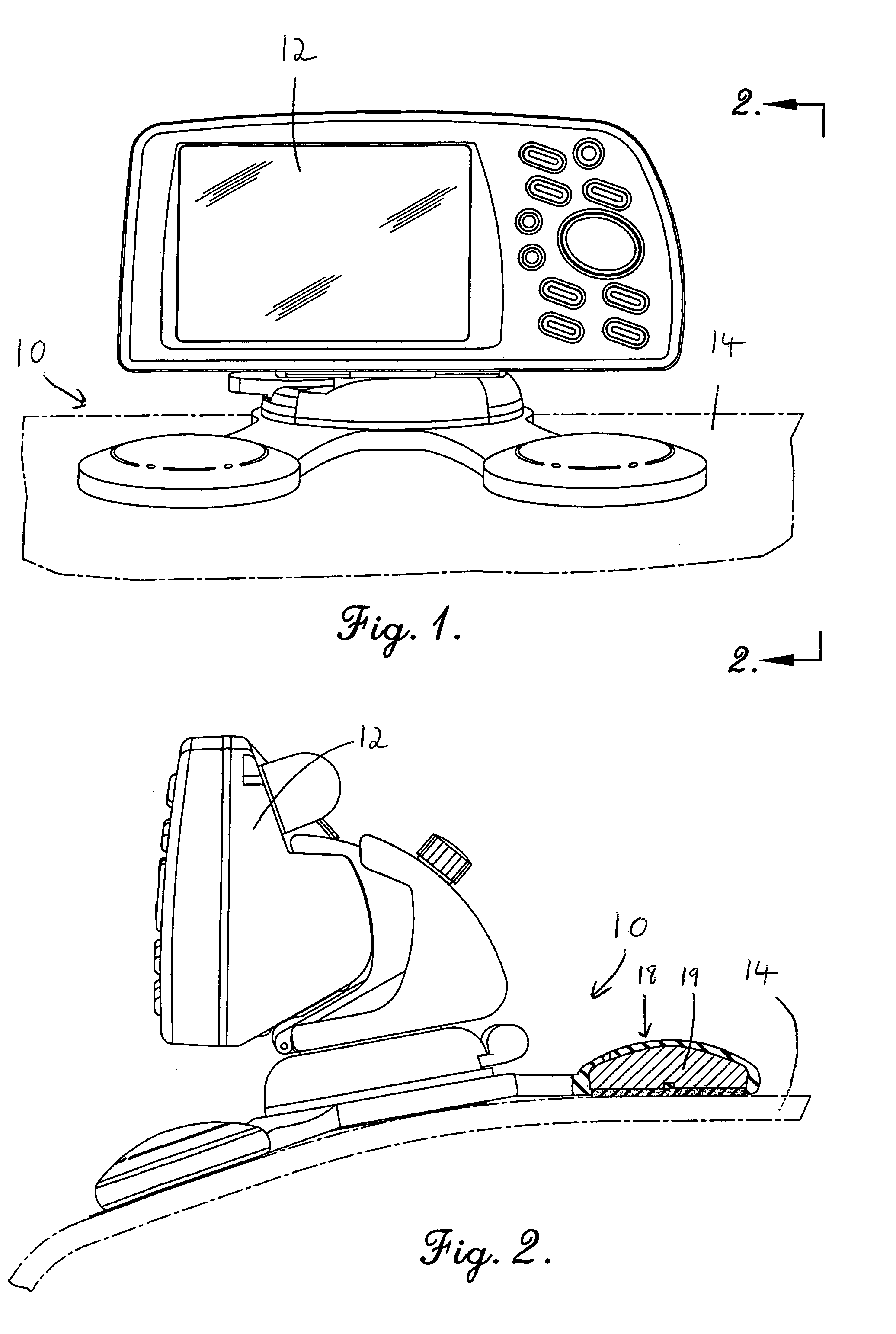
[0021]FIG. 1 is a perspective view of a friction mount apparatus constructed in accordance with a first preferred embodiment of the invention, wherein the apparatus is depicted securing an electronic device to a contoured support surface of a vehicle;

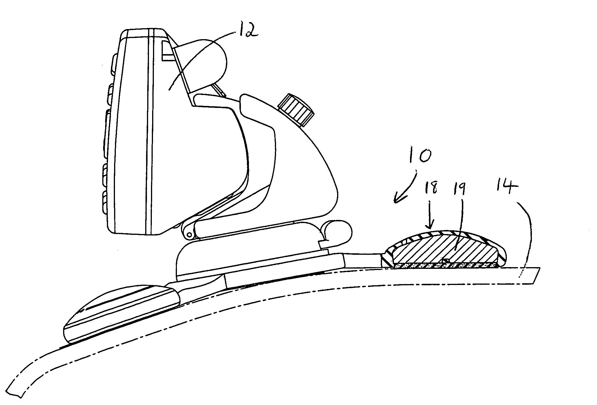
[0022]FIG. 2 is a side elevation view of the device of FIG. 1 showing a cross-sectional view of an anchor of the device;

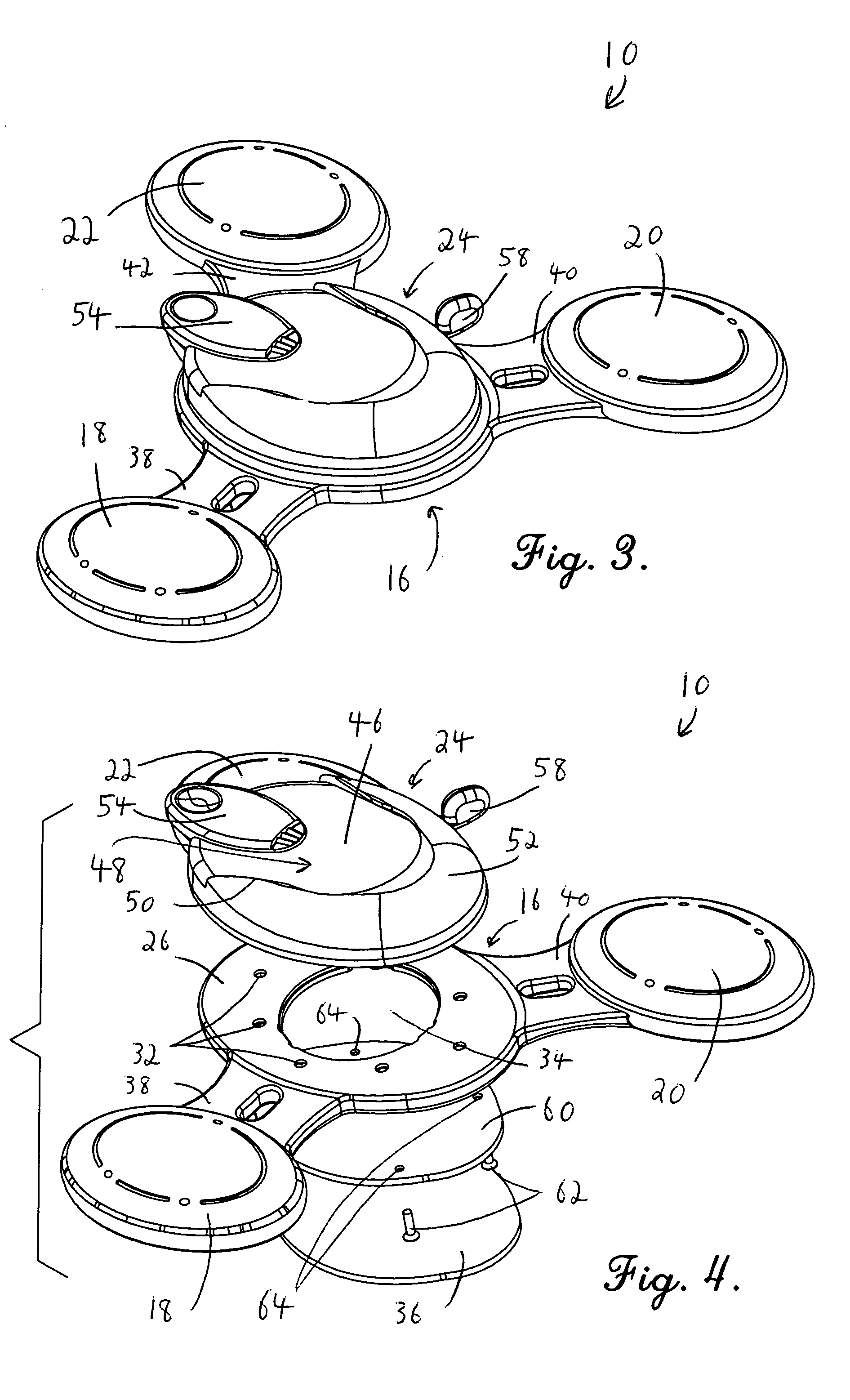
[0023]FIG. 3 is a perspective view of the apparatus of FIG. 1, wherein the apparatus is depicted without the support surface and without the electronic device;

[0024]FIG. 4 is an exploded top perspective view of the apparatus of FIG. 1;

[0025]FIG. 5 is an exploded bottom perspective view of the apparatus of FIG. 1;

[0026]FIG. 6 is a perspective exploded view of a friction mount apparatus constructed in accordance with a second preferred embodime...


PUM


Abstract

A friction mount apparatus for supporting an electronic device (10) on a surface (14). The apparatus (10) includes a body (16), anchors (18,20,22), and a receiving member (24). Body (16) includes a recessed surface (30) on the bottom thereof into which a foam layer (36) is secured, wherein the foam layer (36) contacts a mounting surface (14) and resists moving relative to the surface (14). The anchors (18,20,22) are connected to the body (16) via flexible necks (38,40,42) and have bottom surfaces formed of soft material and weighted cores to press the bottom surfaces against the mounting surface to resist movement relative to the mounting surface (14) and thus further stabilize the apparatus (10). The receiving member (24) is secured to a top surface of the body (16) and is adapted to releasably retain an electronic device (12).

Description

BACKGROUND OF THE INVENTION[0001]1. Field of the Invention[0002]The present invention relates to a mounting apparatus for an electronic device. More specifically, the invention relates to a removable mounting apparatus for an electronic device that is frictionally secured to a support surface, wherein the support surface presents limited surface space and / or includes one or more contours.[0003]2. Description of Prior Art[0004]The use of electronic devices in vehicles has increased in recent years. For example, it is increasingly more common to see electronic devices such as global positioning satellite devices, portable telephones, radios and personal digital assistants (PDAs) mounted within vehicles either permanently or, in the case of portable electronics, removably. Many of these devices have a screen which visibly communicates information to the user thereof. Thus, it is advantageous to be able to adjust the position and the angle of the device to provide maximum viewing capabi...

Claims


Application Information

Patent Timeline
Patent Type & Authority Patents(United States)
IPC IPC(8): A47B91/00
CPCA47B81/065A47B91/02B60R11/02B60R2011/0071B60R2011/005Y10S224/929Y10S248/91
Inventor MUDD, JOHN J.SCHOENFISH, BRIAN G.MINELLI, JEFFREY D.LAVERICK, DAVID J.
Owner GARMIN
Learn More