Wedge thread with torque shoulder

a technology of torque shoulder and wedge thread, which is applied in the direction of screw threaded joints, hose connections, manufacturing tools, etc., can solve the problems of shallow seal angle, inherent wear characteristics, and extreme care required

Inactive Publication Date: 2010-04-06
HYDRIL CO
View PDF16 Cites 38 Cited by
  • Summary
  • Abstract
  • Description
  • Claims
  • Application Information

AI Technical Summary

Benefits of technology

[0005]In one aspect, the present invention relates to a threaded pipe connection including a pin member having an external thread increasing in width in one direction, the external thread including load and stab flanks, a box member having an internal thread increasing in width in the other direction so that complementary internal and external threads move into engagement upon make-up of the connection, the internal thread comprising load and stab flanks, a positive stop torque shoulder, and wherein the width of the internal thread and external thread are selected to provide a selected clearance at least between the internal load and stab flanks and the external load and stab flanks upon initial engagement of the positive stop torque shoulder.

Problems solved by technology

There are, however, a few issues that require extreme care when designing connection using wedge thread technology.
A first issue is designing connections using metal-to-metal sealing interfaces in conjunction with wedge thread technology.
A second issue is the inherent wear characteristics encountered during multiple make and breaks associated with wedge thread technology.
The primary problem encountered when trying to incorporate a wedge thread with a conical metal-to-metal seal in the prior art is that a very shallow seal angle is required to compensate for the linear variability of the wedge thread torque stop.
The second problem encountered using wedge thread technology is determining when the wedge thread begins to wear to a point that the connection is no longer serviceable as a result of repeated make and breaks.

Method used


Image

  • Wedge thread with torque shoulder
  • Wedge thread with torque shoulder
  • Wedge thread with torque shoulder

Examples


Embodiment Construction

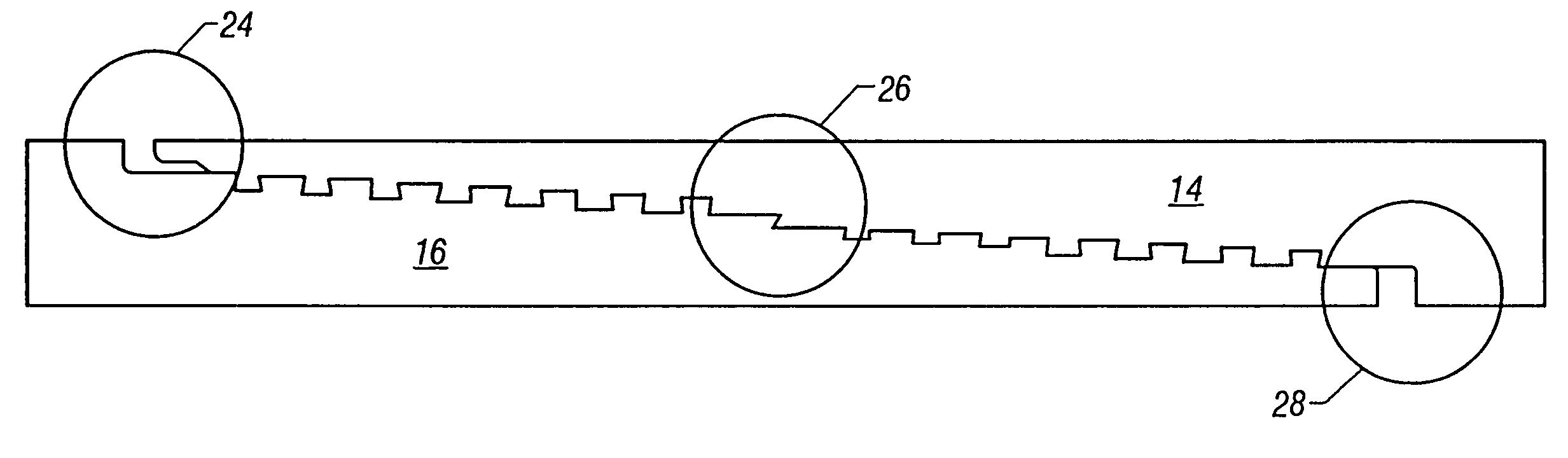
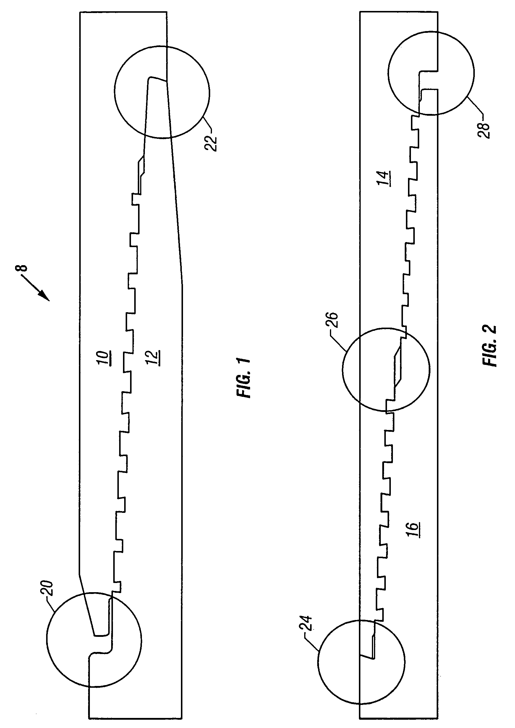
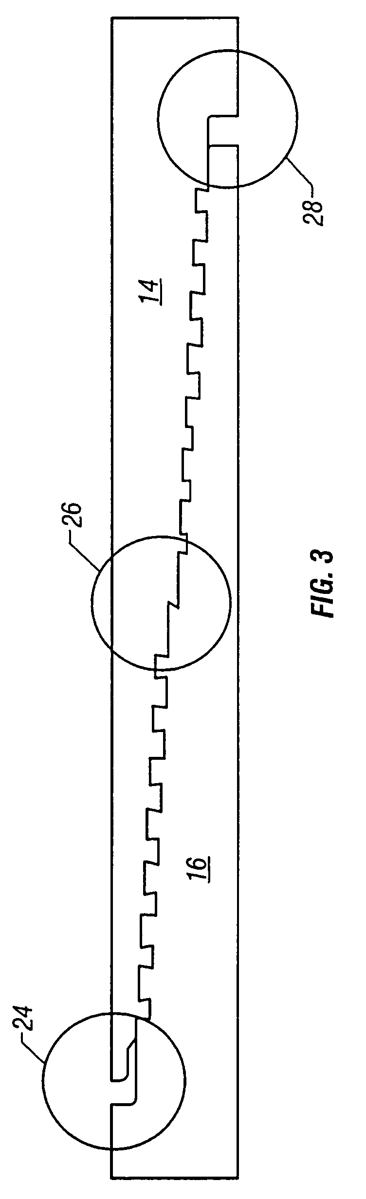
[0024]Referring to the drawings wherein like reference characters are used for like parts throughout the several views, FIGS. 1-3 illustrate a cross section of the wedge thread of a pin member and a box member in accordance with embodiments of the invention. As shown in FIG. 1, in one embodiment, the invention is a one-step wedge thread form with a positive stop torque shoulder. The positive stop torque shoulder can be located at the interface of the pin nose / box inner diameter (ID) shoulder, as shown in FIG. 1, or located at the interface of the box face / pin outer diameter (OD) shoulder.

[0025]Connection 8 includes a box member 10 and a pin member 12. Box member 10 has a tapered, internal, generally dovetail-shaped thread structure formed thereon and adapted for engaging complementary tapered, external, generally dovetail-shaped thread structure formed on pin member 12 to mechanically secure the box and pin members in a releasable manner.

[0026]Internal thread of box member 10 has st...


PUM

PropertyMeasurementUnit
angleaaaaaaaaaa
widthaaaaaaaaaa
plastic deformationaaaaaaaaaa

Abstract

A threaded pipe connection including a pin member having an external thread increasing in width in one direction, the external thread including load and stab flanks, a box member having an internal thread increasing in width in the other direction so that complementary internal and external threads move into engagement upon make-up of the connection, the internal thread comprising load and stab flanks, a positive stop torque shoulder, and wherein the width of the internal thread and external thread are selected to provide a selected clearance at least between the internal load and stab flanks and the external load and stab flanks upon initial engagement of the positive stop torque shoulder is disclosed.

Description

CROSS-REFERENCE TO RELATED APPLICATIONS[0001]This application is a continuation-in-part application of U.S. application Ser. No. 09 / 294,889, filed Apr. 19, 1999 now abandoned.FIELD OF THE INVENTION[0002]The invention relates to threaded tubular joints usable in oil and gas well drilling and production, such as tubing, casing, line pipe, and drill pipe, commonly known collectively as oilfield tubular goods. More particularly, the invention relates to wedge thread having a positive stop torque shoulder for connecting male (pin) and female (box) members.BACKGROUND OF THE INVENTION[0003]The use of threaded tubular connections for joining flow conduits in an end-to-end relationship to form a continuous flow path for transporting fluid under pressure is well known. Oilfield tubular goods all use threaded connections for connecting adjacent sections of conduit or pipe. Examples of such threaded end connections designed for use on oilfield tubular goods are disclosed in U.S. Pat. Nos. 2,239...

Claims


Application Information

Patent Timeline
Patent Type & Authority Patents(United States)
IPC IPC(8): F16L25/00E21B17/042F16L15/06
CPCE21B17/0423F16L15/004Y10T29/49881E21B17/042
Inventor MALLIS, DAVID LLEWELLYNREYNOLDS, HARRIS ALLEN
Owner HYDRIL CO
Why Eureka
Try Eureka