Surface light source device

a light source and surface technology, applied in semiconductor devices, lighting and heating devices, instruments, etc., can solve problems such as color unevenness, luminance unevenness, color unevenness, etc., to prevent luminance unevenness and increase display quality.

Active Publication Date: 2010-04-06
MITSUBISHI ELECTRIC CORP +1
View PDF16 Cites 18 Cited by
  • Summary
  • Abstract
  • Description
  • Claims
  • Application Information

AI Technical Summary

Benefits of technology

[0011]With this configuration, since the incident surface of the light guide plate is inclined toward the back side, the proportion of light that shines on the incident surface from each point light source and is then refracted toward the front surface can be made larger than in the case that the inclination angle is not inclined toward the back side. Therefore, the quantity of light that travels directly from the incident surface to the light diffusing means provided on the back surface of the light guide plate can be decreased. This makes it possible to prevent light beams emitted from the point light sources from being diffused in their vicinities without being mixed together sufficiently.
[0012]In particular, an inclination angle of a back side portion of the incident surface of the light guide plate is larger than that of a front-side portion of the incident surface. This configuration can prevent light beams emitted from the point light sources from being diffused in their vicinities without being mixed together sufficiently, and can also prevent light that is input through a front portion of the incident surface from being output from the light guide plate instead of being totally reflected by a portion, in the vicinity of the point light sources, of the front surface of the light guide plate.
[0016]According to the surface light source device according to the invention, since a larger proportion of light that shines on the incident surface from each point light source is refracted toward the front surface, the quantity of light that travels directly from the incident surface to the light diffusing means provided on the back surface of the light guide plate can be decreased. This makes it possible to prevent light beams emitted from the point light sources from being diffused in their vicinities without being mixed together sufficiently, which in turn makes it possible to prevent luminance unevenness and color unevenness from occurring in a region close to the point light sources in their arrangement direction and to thereby increase the display quality.

Problems solved by technology

Side-light-type surface light source devices that employ plural point light sources as light-emitting elements have a problem that luminance unevenness or color unevenness may occur in a region close to the point light sources in their arrangement direction.
In particular, where LEDs that emit light beams of plural colors (R (red), G (green), and B (blue)) are used as point light source, light beams emitted from the point light sources of the different colors are not mixed together sufficiently and hence color unevenness may occur in addition to luminance unevenness.
Luminance unevenness or color unevenness results in a problem that the display quality of a display panel is lowered.
As described above, conventional surface light source devices have the problem that luminance unevenness or color unevenness may occur in a region close to point light sources in their arrangement direction.

Method used


Image

  • Surface light source device
  • Surface light source device
  • Surface light source device

Examples


embodiment 1

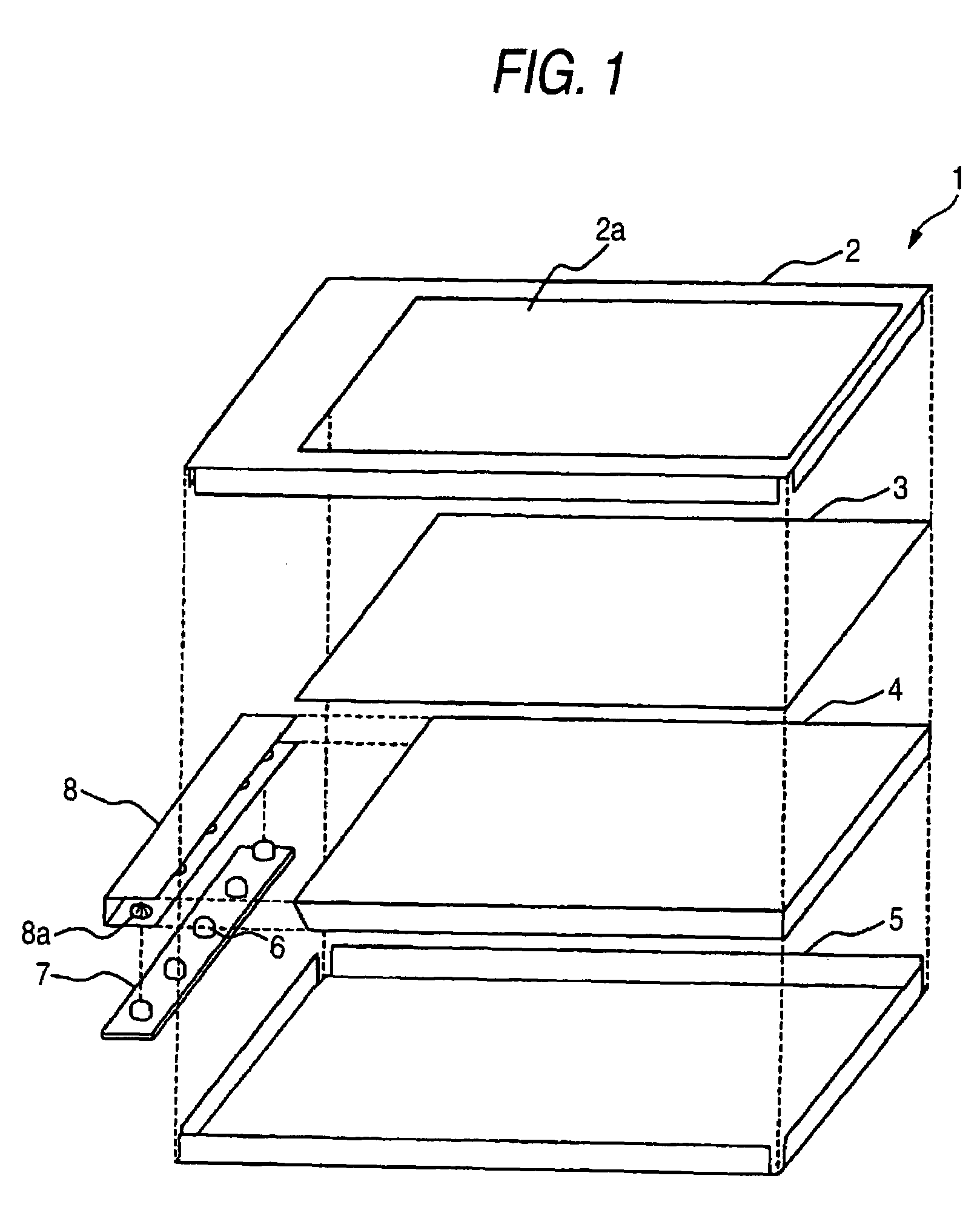
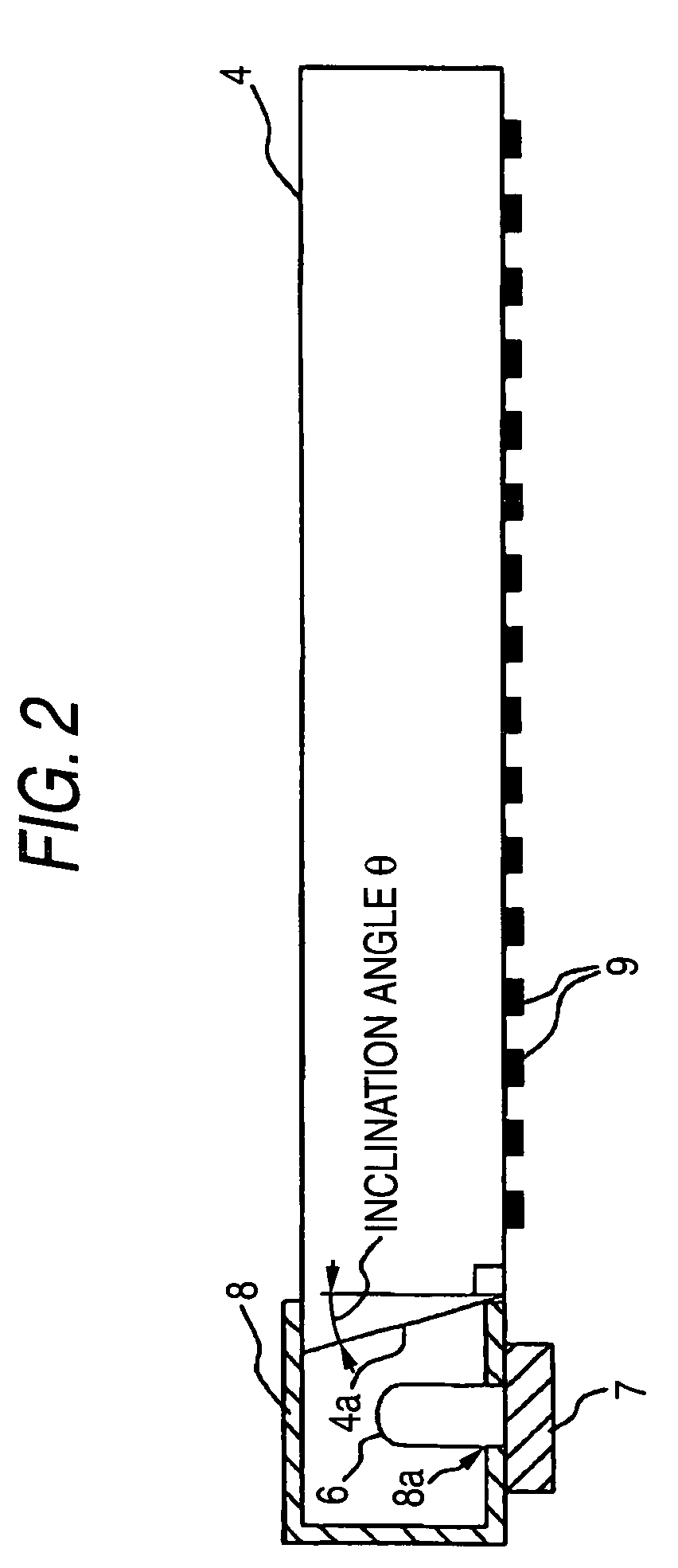
[0028]FIG. 1 is an exploded perspective view outlining the configuration of a surface light source device according to a first embodiment of the present invention. A surface light source device 1 according to this embodiment is a side-light-type surface light source device having a light guide plate 4 that outputs, from its front surface, light that is input from plural LEDs 6 that are arranged linearly. The surface light source device 1 is suitable to illuminate a display panel such as a liquid crystal panel over its entire display area with uniform light. The term “display panel” as used herein means a display device for displaying various kinds of information and encompasses things other than a liquid crystal panel, such as a display board (e.g., signboard).

[0029]The surface light source device 1 is composed of a front frame 2, an optical sheet 3, the light guide plate 4, a rear frame 5, and a light source unit. The light source unit is composed of LEDs (light-emitting diodes) 6 ...

embodiment 2

[0045]The first embodiment is directed to the case that the incident surface 4a of the light guide plate 4 is inclined toward the back side. In contrast, a second embodiment is directed to a case that the inclination angle of a back side portion of the incident surface is larger than that of a front-side portion of the incident surface.

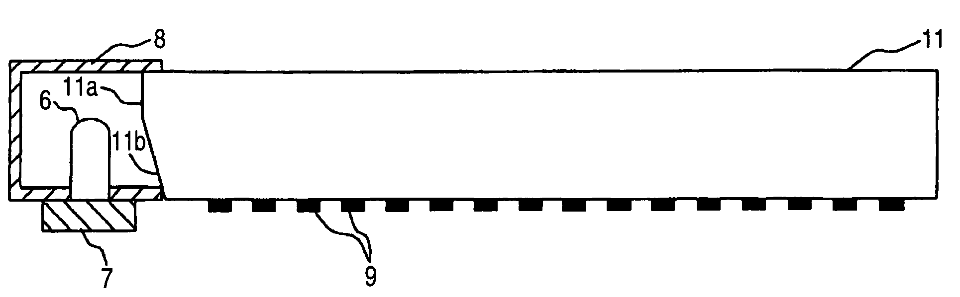
[0046]FIG. 5 is a sectional view showing the details of an important part of an exemplary surface light source device according to the second embodiment of the invention, and shows an incident surface of a light guide plate 11 that includes two planes that are different in the inclination angle θ. The incident surface of the light guide plate 11 includes two light entrance surfaces 11a and 11b that are different in the inclination angle θ, and the inclination angle θ increases as the position goes away from the front surface of the light guide plate 11. That is, the inclination angle θ of the back side light entrance surface 11b is larger than that of...

embodiment 3

[0052]The second embodiment is directed to the case that the incident surface of the light guide plate 11 includes plural planes that are different in the inclination angle θ. In contrast, a third embodiment is directed to a case that the incident surface is a curved surface.

[0053]FIG. 7 is a sectional view showing the details of an important part of an exemplary surface light source device according to the third embodiment of the invention, and shows an incident surface 21a of a light guide plate 21 that is a curved surface whose inclination angle θ increases as the position goes away from the front surface of the light guide plate 21. The incident surface 21a of the light guide plate 21 is a curved surface whose inclination angle θ varies continuously, that is, increases as the position goes away from the front surface of the light guide plate 21. The shape of the curved surface of the incident surface 21a is determined in accordance with required display performance. For example,...


PUM


Abstract

A surface light source device includes two or more point light sources that are arranged linearly, a light guide plate having an incident surface on which light emitted from each of the point light sources shines, for outputting input light from a front surface thereof, and light diffusing means provided on a back surface of the light guide plate, for diffusing light. The incident surface of the light guide plate is inclined toward a back side.

Description

BACKGROUND OF THE INVENTION[0001]1. Field of the Invention[0002]The present invention relates to a surface light source device and, more specifically, to improvement of a surface light source device having a light guide plate for outputting, from its front surface, input light that is input through its incident surface from plural point light sources that are arranged linearly.[0003]2. Description of the Related Art[0004]Surface light source devices are known that illuminate a display panel such as a liquid crystal panel over its entire display area with uniform light. Surface light source devices of this type are classified into a direct type in which a light-emitting element(s) is disposed in the rear of a body and a side light type (also called an edge light type) in which a light-emitting element(s) is disposed in a side portion of a body. Further, side-light-type surface light source devices are classified into a type in which a linear light source such as a CCFL (cold cathode ...

Claims


Application Information

Patent Timeline
Patent Type & Authority Patents(United States)
IPC IPC(8): F21V7/04
CPCG02B6/0013F21Y2103/003G02B6/0021F21Y2101/02G02B6/0073G02B6/0091G02B6/0065F21Y2103/10F21Y2115/10
Inventor MORI, AKIHIROYONEDA, TOSHIYUKI
Owner MITSUBISHI ELECTRIC CORP
Why Eureka
Try Eureka