
Vignetting compensation

a compensation and vignetting technology, applied in the field of image processing, can solve the problems of unworkable and inacceptable last case, unsatisfactory, and all camera lenses suffering, more or less, of these optical phenomena, and use of typically complex optical systems

Active Publication Date: 2010-04-06
GULA CONSULTING LLC
View PDF22 Cites 12 Cited by
  • Summary
  • Abstract
  • Description
  • Claims
  • Application Information

AI Technical Summary

Problems solved by technology

All camera lenses suffer, more or less, of these optical phenomena.
Obviously the last case is unworkable and is not acceptable.
In order to solve said problems with vignetting, cameras are using typically complex optical systems, which are very expensive to manufacture.
It is a challenge for the designers of digital cameras to design a camera having very low vignetting using less expensive lenses.

Method used


Image

  • Vignetting compensation
  • Vignetting compensation
  • Vignetting compensation

Examples


Embodiment Construction

[0020]The preferred embodiments disclose a method to compensate the vignetting of digital cameras allowing the usage of a cheaper lens with high image quality in respect of vignetting.

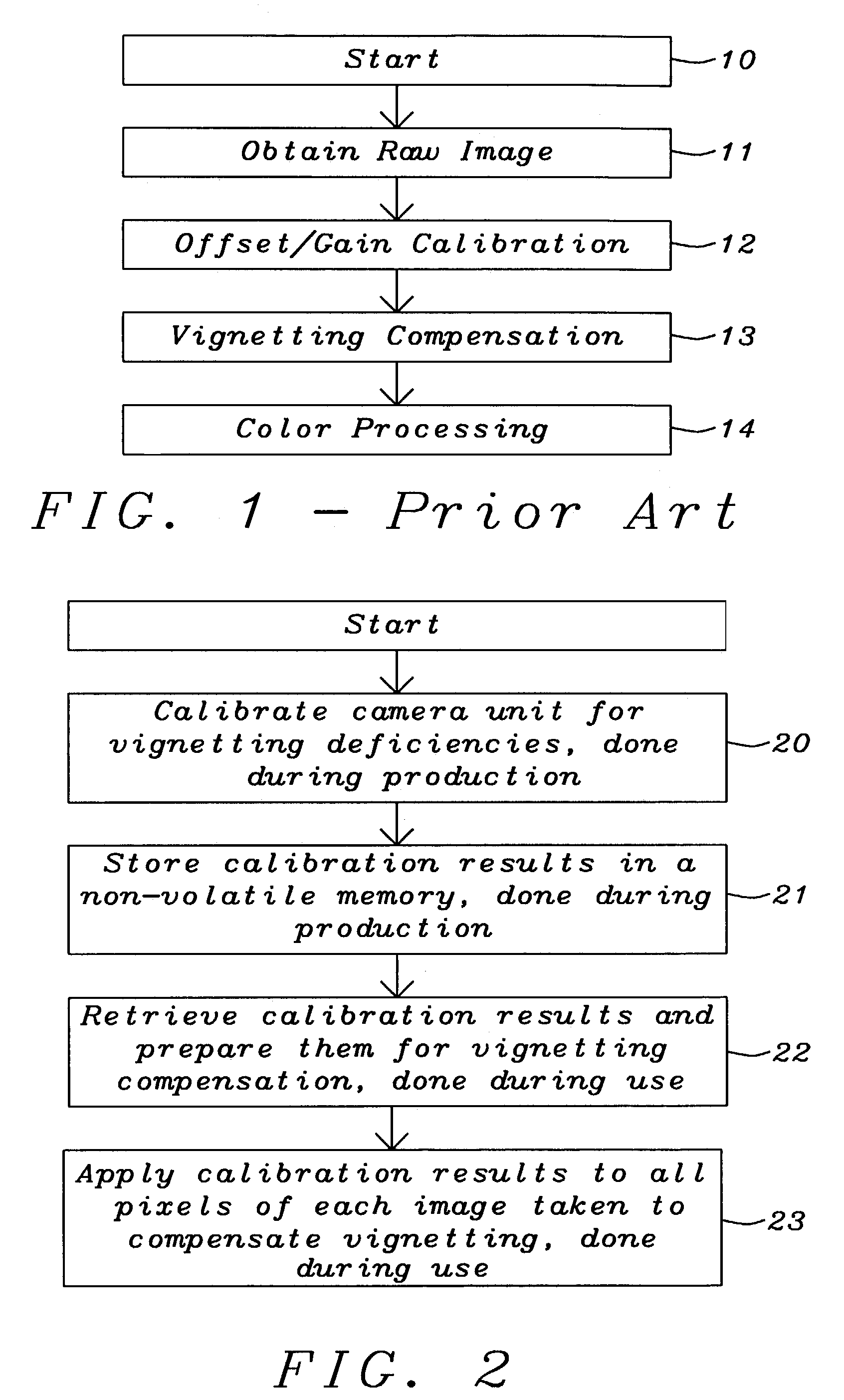
[0021]FIG. 2 describes the general method of a preferred embodiment to compensate vignetting. Said method comprises two phases. In the first phase the camera unit is calibrated. Said calibration is performed only once during production of a camera unit and it comprises two major steps 20 and 21. In step 20 the camera unit is calibrated for vignetting deficiencies and in step 21 the result of said calibration is stored in a non-volatile memory of the camera. The second phase comprises the application of the calibration results to all pixels of each image taken. In step 22 said calibration results are retrieved from said non-volatile memory and prepared to be applied to each image taken. In step 23 said calibration data prepared are applied to all pixels of each image taken to compensate vignetting.

[0022...


PUM


Abstract

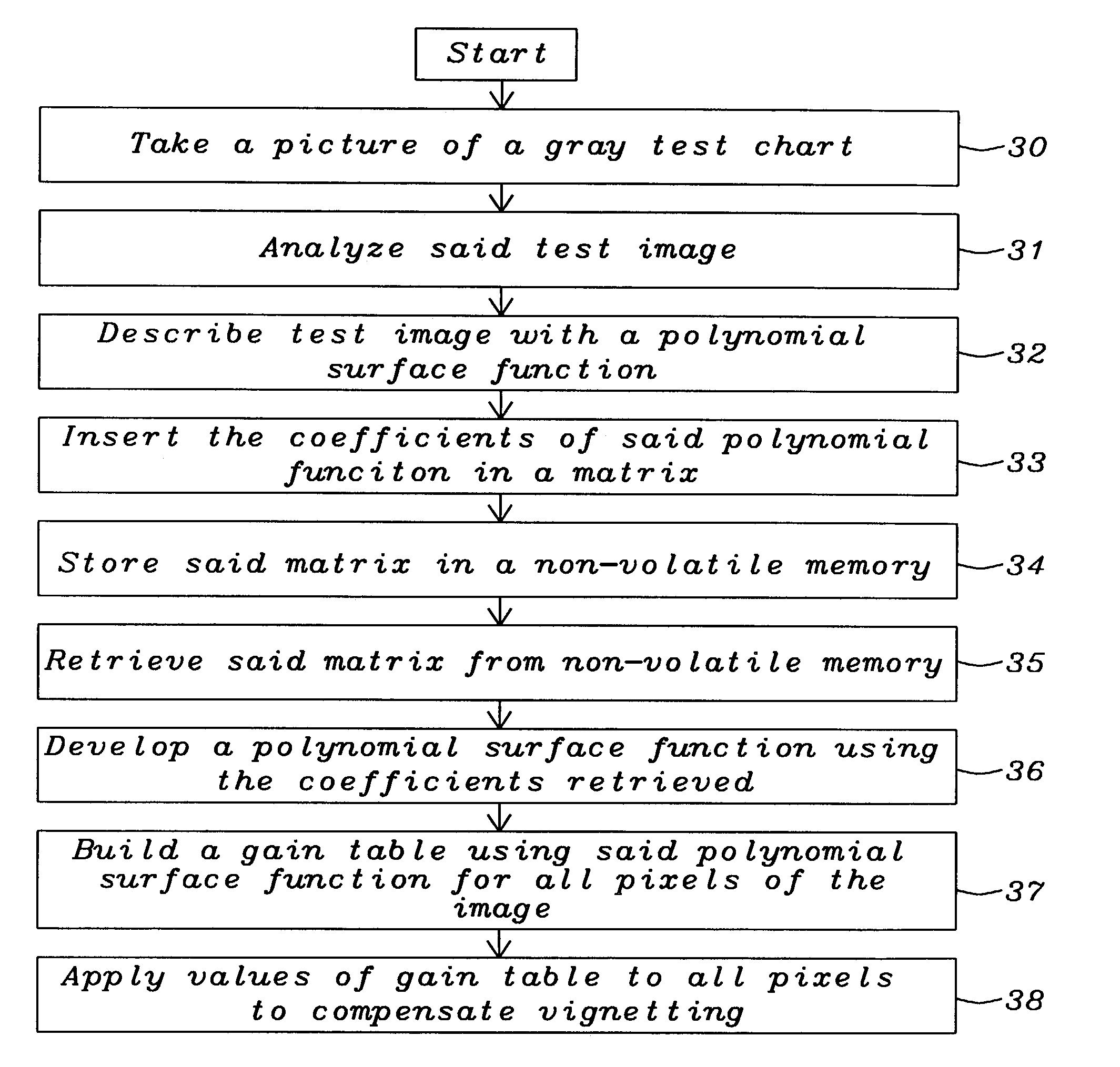
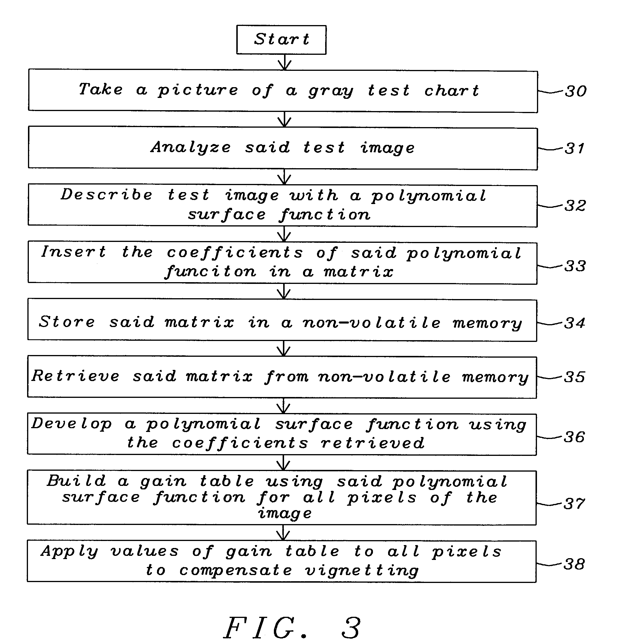
A method used for the compensation of vignetting in digital cameras has been achieved. The compensation for vignetting is done in two steps. The first step is done during production of the camera unit and involves taking and analyzing an image of a test screen, preferably a gray test screen. This results in a set of e.g. 5×5 coefficients describing a polynomial surface. The second step is done for each image that is taken by the camera and involves calculating and applying a gain-table based on polynomial coefficients to all pixels of the image to compensate vignetting.

Description

BACKGROUND OF THE INVENTION[0001](1) Field of the Invention[0002]This invention relates generally to image processing and relates more particularly to a method to compensate vignetting in digital images.[0003](2) Description of the Prior Art[0004]Photographically, vignetting means the darkening of the corners relative to the centre of an image. All camera lenses suffer, more or less, of these optical phenomena.[0005]FIG. 1 prior art describes some major steps performed in image processing. In the first step10 a raw image is obtained. In the next step 11 the offset / gain calibration is performed, followed by the compensation for vignetting 12. The last step 13 is the color processing.[0006]A simple lens obeys an optical law called the “cos-4th law” (cosine of the angle of incidence off the lens axis to the 4th power. The cos-4th influence comes from a number of factors, including that the light gets spread out over a larger area, and that the corners of the image are further away from...

Claims


Application Information

Patent Timeline
Patent Type & Authority Patents(United States)
IPC IPC(8): H04N9/64G06T3/00H04N5/20H04N23/76
CPCH04N5/3572H04N25/61E04H6/42
Inventor JOHANNESSON, ANDERSLARSSON, INGEMAR
Owner GULA CONSULTING LLC
Learn More