Methods and systems for eliminating deleterious polarization effects in an optical fiber dispersion compensation module

a technology of optical fiber and dispersion compensation, applied in the field of optical communication networks, can solve the problems of limited transmission data rate for a given link length, all conventional optical fiber dcms suffer from lack of polarization control, etc., and achieve the effects of reducing polarization change, reducing polarization change, and reducing polarization chang

Active Publication Date: 2010-04-06
CIENA
View PDF6 Cites 15 Cited by
  • Summary
  • Abstract
  • Description
  • Claims
  • Application Information

AI Technical Summary

Benefits of technology

[0006]In another exemplary embodiment of the present invention, a system for mitigating polarization changes associated with an optical communication signal caused by mechanical disturbances to an optical fiber dispersion compensation module of an optical communication network includes: a housing associated with the optical fiber dispersion compensation module; an optical fiber disposed within the housing associated with the optical fiber dispersion compensation module; and a first damping material disposed between the optical fiber and the housing associated with the optical fiber dispersion compensation module; wherein the first damping material is selected and positioned such that it mitigates relatively fast polarization changes. Preferably, the system also includes a clamp for holding the first damping material and a spool holding the optical fiber adjacent to the housing. Optionally, the system further includes a second damping material disposed between the optical fiber and the housing associated with the optical fiber dispersion compensation module; wherein the second damping material is selected and positioned such that it mitigates relatively slow polarization changes. Optionally, the system still further includes a spool holding the optical fiber adjacent to the second damping material. Again, the optical fiber consists of dispersion compensation fiber.
[0007]In a further exemplary embodiment of the present invention, a method for mitigating polarization changes associated with an optical communication signal caused by mechanical disturbances to an optical fiber dispersion compensation module of an optical communication network includes: disposing a damping material between one or more of a) an optical fiber and a housing associated with the optical fiber dispersion compensation module and b) the housing associated with the optical fiber dispersion compensation module and an electronics rack on which the housing associated with the optical fiber dispersion compensation module is disposed; wherein the damping material is selected and positioned such that it mitigates one or more of relatively fast and relatively slow polarization changes.
[0008]In a still further exemplary embodiment of the present invention, a system for mitigating polarization changes associated with an optical communication signal caused by mechanical disturbances to an optical fiber dispersion compensation module of an optical communication network includes: a housing associated with the optical fiber dispersion compensation module; an optical fiber disposed within the housing associated with the optical fiber dispersion compensation module; and a damping material disposed between one or more of a) the optical fiber and the housing associated with the optical fiber dispersion compensation module and b) the housing associated with the optical fiber dispersion compensation module and an electronics rack on which the housing associated with the optical fiber dispersion compensation module is disposed; wherein the damping material is selected and positioned such that it mitigates one or more of relatively fast and relatively slow polarization changes.

Problems solved by technology

As a result of the PMD associated with the optical fibers and other components of an optical communications network, the transmission data rate for a given link length is limited.
All conventional optical fiber DCMs suffer from this lack of polarization control.

Method used


Image

  • Methods and systems for eliminating deleterious polarization effects in an optical fiber dispersion compensation module
  • Methods and systems for eliminating deleterious polarization effects in an optical fiber dispersion compensation module
  • Methods and systems for eliminating deleterious polarization effects in an optical fiber dispersion compensation module

Examples


Embodiment Construction

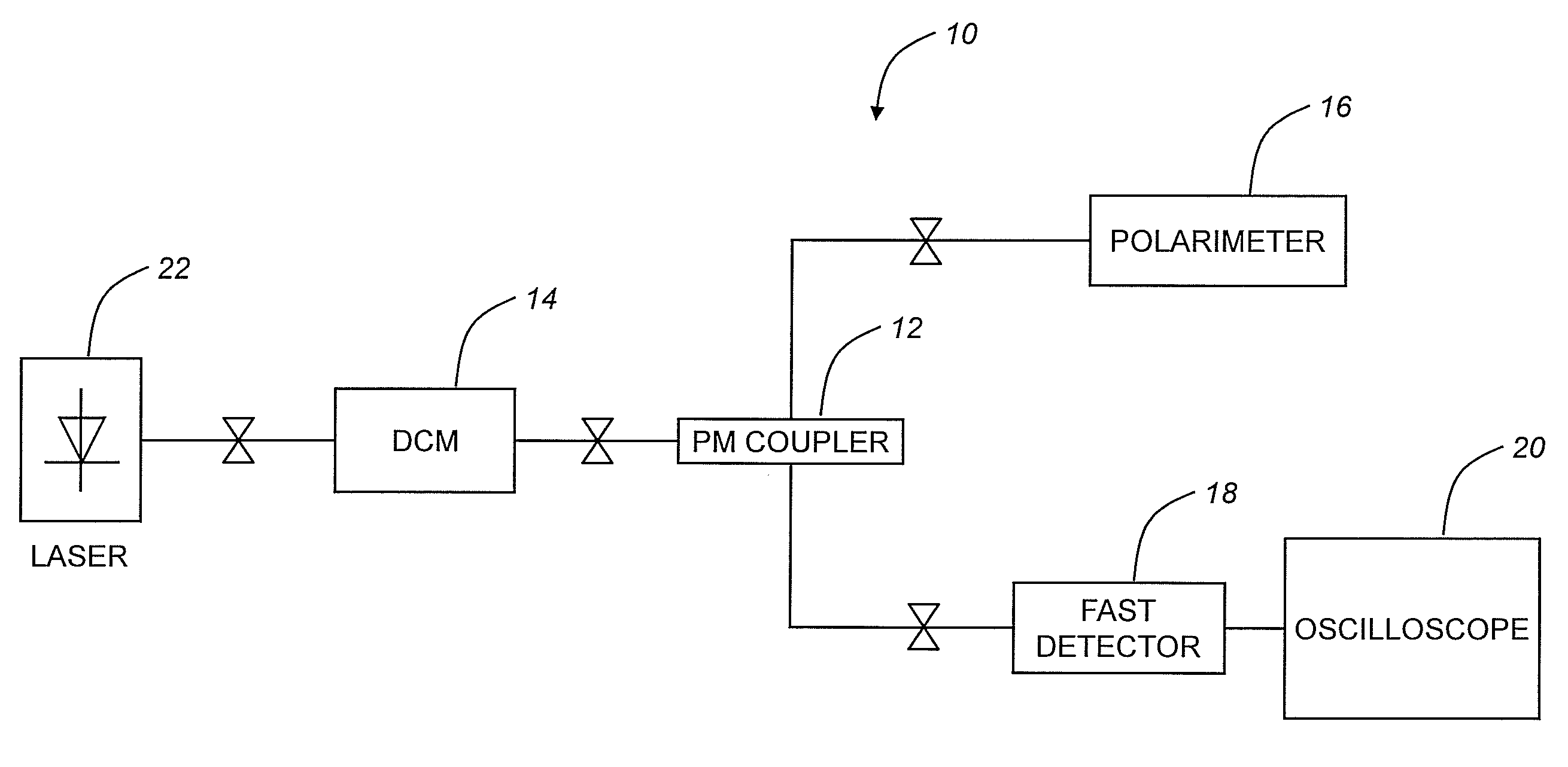
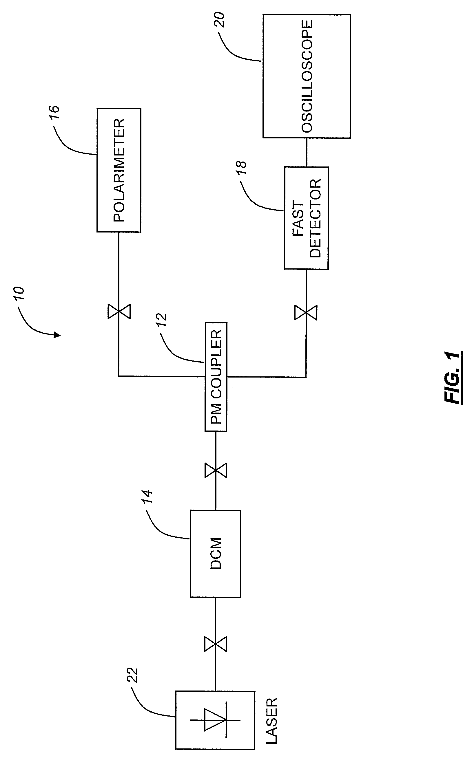
[0017]As described above, the current state of the art in dispersion compensation is based on introducing optical fiber DCMs along the optical path and at the optical links. Although some attempts are being made to use different technologies (e.g. optical fiber Bragg gratings, etalons, etc.), most routes now use optical fiber DCMs. Given the length of DCF required for compensation, these modules are especially susceptible to shock, which translates into changes in the polarization state of the output beam. Typically, these changes can be quite fast, and difficult to track and correct for with a PMDC or the like. Similar problems can be encountered in optical fiber transmission systems using polarization multiplexing (Pol-Mux), in the case where a polarization controller (PC) and polarization tracker are used to demultiplex two polarized signals.

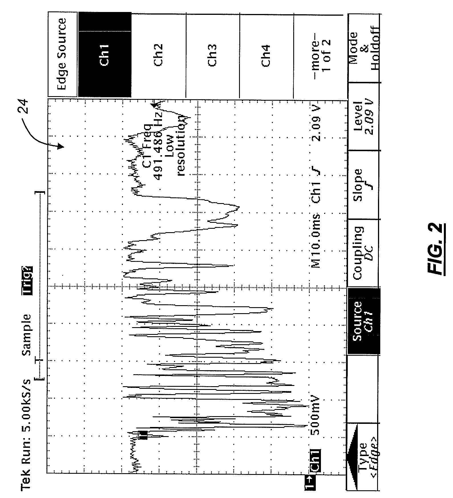
[0018]Preliminary measurements have shown that the rate of polarization change with shock acceleration points to DCMs as a major problem for...


PUM


Abstract

The present invention provides methods and systems for mitigating polarization changes associated with an optical communication signal caused by mechanical disturbances to an optical fiber dispersion compensation module of an optical communication network. The methods include disposing a first damping material between an optical fiber and a housing associated with the optical fiber dispersion compensation module; wherein the first damping material is selected and positioned such that it mitigates relatively fast polarization changes. Optionally, the methods also include disposing a second damping material between the optical fiber and the housing associated with the optical fiber dispersion compensation module; wherein the second damping material is selected and positioned such that it mitigates relatively slow polarization changes. Thus, frequency range specific optical fiber dispersion compensation module mechanical perturbation isolation methods and systems are provided.

Description

FIELD OF THE INVENTION[0001]The present invention relates generally to optical communication networks. More specifically, the present invention relates to methods and systems for eliminating deleterious polarization effects in an optical fiber dispersion compensation module (DCM).BACKGROUND OF THE INVENTION[0002]Polarization mode dispersion (PMD) is a physical effect caused by the inherent birefringence of optical materials. In optical fibers, this inherent birefringence is induced by several factors, including manufacturing imperfections and stresses, microbends, and the like. As a result of the PMD associated with the optical fibers and other components of an optical communications network, the transmission data rate for a given link length is limited. Projects aimed at controlling the PMD associated with optical links are being undertaken at laboratories around the world. For example, polarization mode dispersion compensators (PMDCs) and the like are being developed.[0003]In orde...

Claims


Application Information

Patent Timeline
Patent Type & Authority Patents(United States)
IPC IPC(8): G02B6/00H04J14/02
CPCG02B6/02214G02B6/44G02B6/02285
Inventor MARRAKCHI EL FELLAH, ABDELLATIFARCHAMBAULT, JEAN-LUCFRANKEL, MICHAEL Y.CHILDERS, MARK
Owner CIENA
Why Eureka
Try Eureka