Horizontal fiber optic patching assembly

a fiber optic and assembly technology, applied in the field of horizontal fiber optic patching assembly, can solve the problems of preventing further use, not including an alignment sleeve, and affecting the quality of optical fiber ports,

Active Publication Date: 2010-04-13
LEGRAND DPC LLC
View PDF29 Cites 119 Cited by
  • Summary
  • Abstract
  • Description
  • Claims
  • Application Information

AI Technical Summary

Benefits of technology

[0015]The presently disclosed patching assemblies and methods present many advantages over prior art. For example, the horizontally-aligned configuration of the ports advantageously increases fiber optic patching density within a cabinet structure while maintaining port accessibility.

Problems solved by technology

An MT-RJ adapter, however, does not include an alignment sleeve because the fibers are aligned by precision pins and holes on the mating connector ferrules.
This configuration disadvantageously prevents further use in the deeper portions associated with cavity 2.
Since the density of fiber optic ports is substantially limited, a relatively large number of cabinets is often necessary to appropriately accommodate a particular data center.

Method used


Image

  • Horizontal fiber optic patching assembly
  • Horizontal fiber optic patching assembly
  • Horizontal fiber optic patching assembly

Examples


Embodiment Construction

)

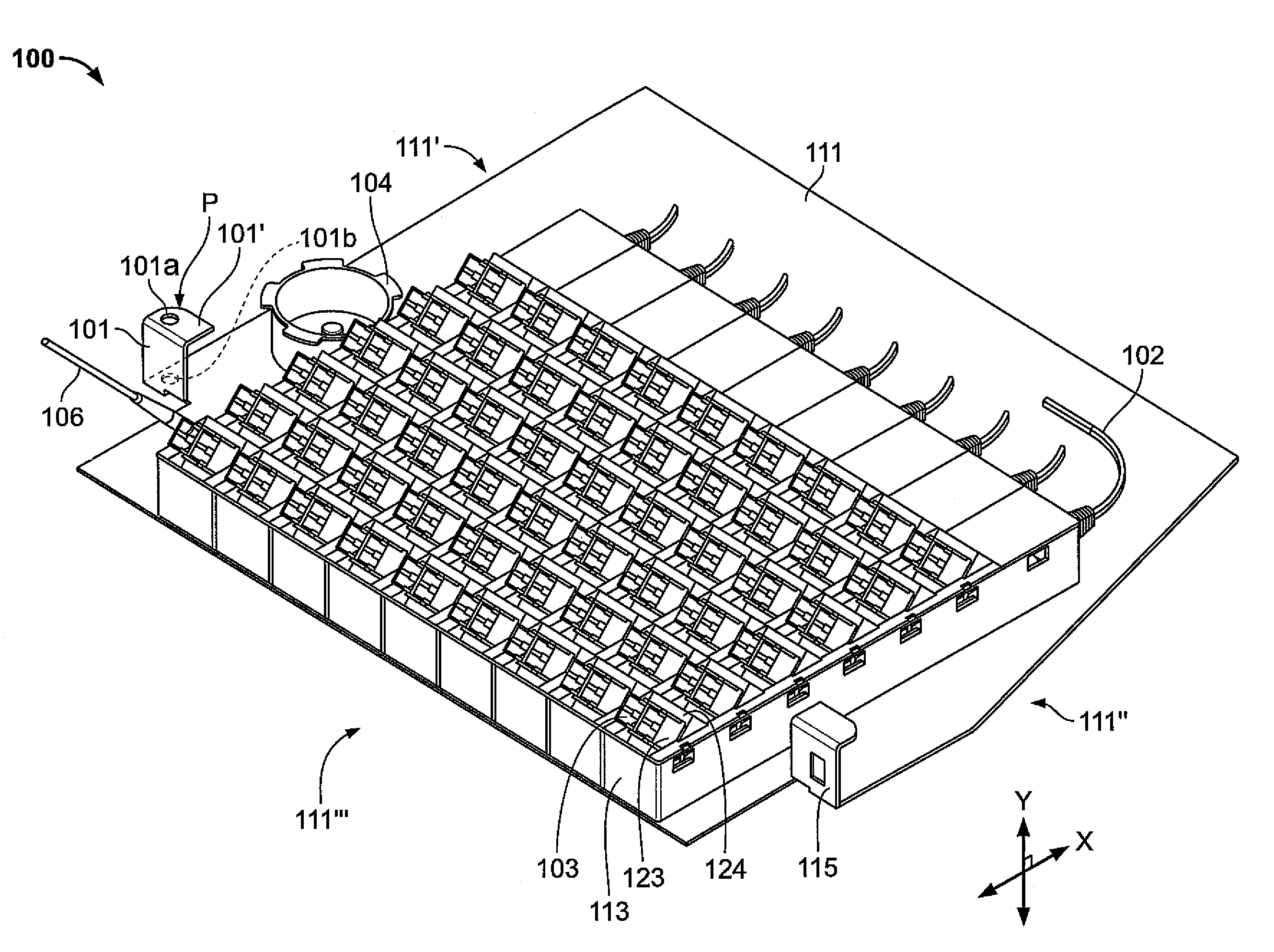
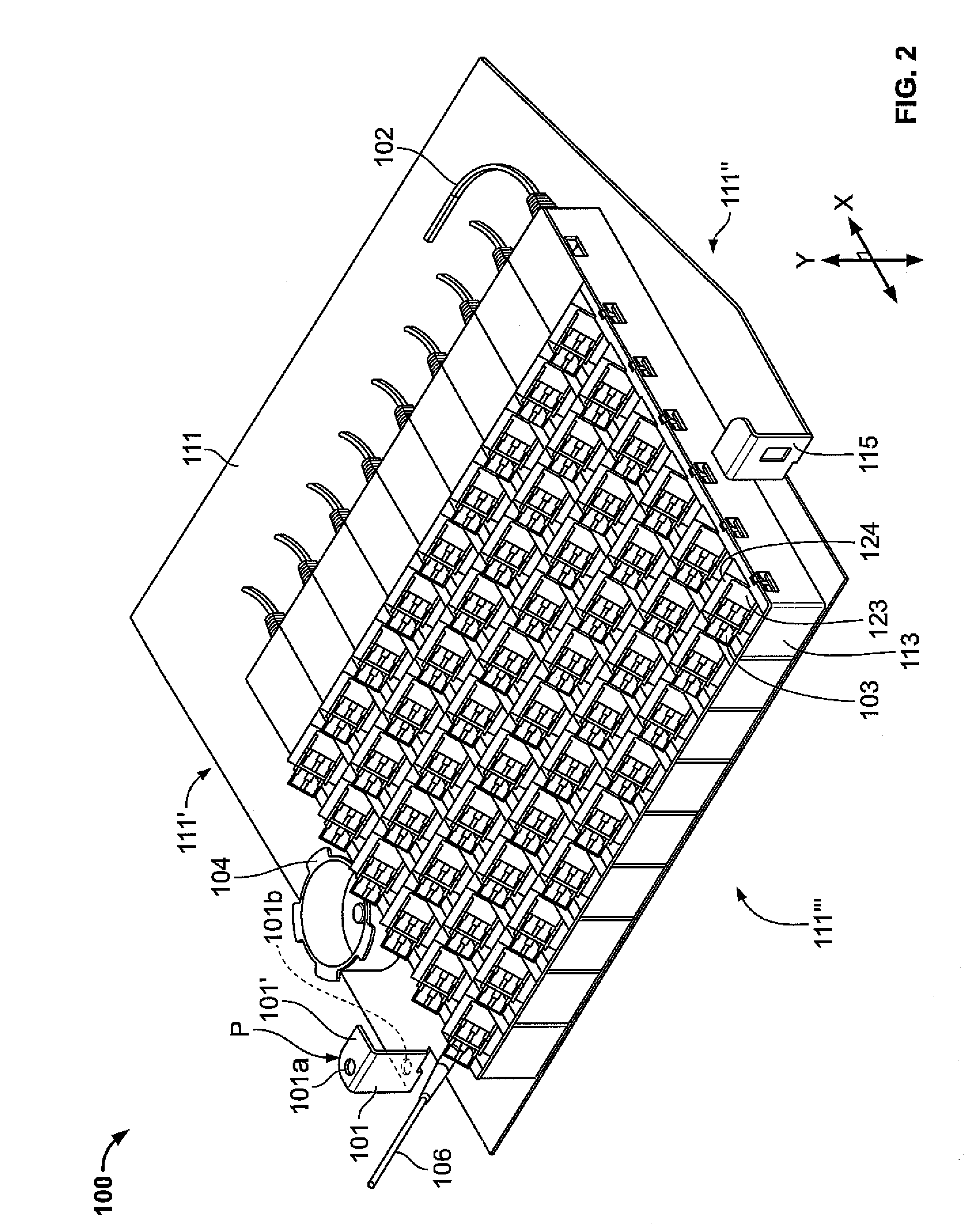
[0026]According to the present disclosure, advantageous assemblies and methods are provided for facilitating fiber optic patching. More particularly, the disclosed assemblies and methods generally involve mounting fiber optic patch ports arranged along a horizontal plane (horizontally-aligned) with respect to a tray. The tray is movably positioned within a cabinet enclosure, e.g. via a pivotal or translational (sliding) relationship, thereby providing easy access to the ports. Thus, the horizontally-aligned configuration advantageously increases fiber optic patching density within a cabinet structure while maintaining port accessibility. In exemplary embodiments, the ports are organized / arranged in defined structures, e.g., quad structures and / or defined configurations, e.g., pairing transmission ports with receiving ports. The ports may also be organized in cassette casings (with or without plug-and-go capabilities). Such port organizations / arrangements advantageously facilitate m...


PUM


Abstract

Assemblies and methods are provided for facilitating fiber optic patching. More particularly, the assemblies and methods generally involve mounting fiber optic patch ports arranged along a horizontal plane with respect to a tray. The tray is movably positioned within a cabinet enclosure, e.g., in a pivotal or translational (sliding) relationship, thereby providing easy access to the ports. The horizontal configuration advantageously increases fiber optic patching density within a cabinet structure while maintaining port accessibility.

Description

BACKGROUND[0001]1. Technical Field[0002]The present disclosure relates to assemblies and methods directed to fiber optic patching arrays.[0003]2. Background Art[0004]Fiber optic patching systems have become more prevalent in the structured cabling market as the need for high speed applications continues to grow. In some cases, fiber optic patching systems have displaced legacy copper patching systems as the need for bandwidth has exceeded the theoretical maximums associated with copper. In central offices, data centers and other wired buildings, fiber optic patch panels have become a necessary media to route connections between switches, servers, storage devices and the general office area. By ‘patching’, or temporarily creating a connection between physically mated connectors, it is possible to reconfigure network connections from a central location.[0005]As shown in the Telecommunication Industry of America (TIA) Standard for Data centers, TIA-942, a patch panel interface frequent...

Claims


Application Information

Patent Timeline
Patent Type & Authority Patents(United States)
IPC IPC(8): G02B6/00
CPCG02B6/4452
Inventor MURANO, ADAMRYNASKI, CHESTER H.
Owner LEGRAND DPC LLC
Why Eureka
Try Eureka