Aircraft installation arrangement and installation system for mounting an overhead luggage compartment

an installation arrangement and luggage compartment technology, applied in the direction of aircraft components, transportation and packaging, aircraft crew accommodation, etc., can solve the problems of time-consuming and expensive maintenance, and achieve the effect of simplifying the mounting of the overhead luggage compartmen

Active Publication Date: 2020-04-21
AIRBUS OPERATIONS GMBH
View PDF11 Cites 2 Cited by
  • Summary
  • Abstract
  • Description
  • Claims
  • Application Information

AI Technical Summary

Benefits of technology

[0006]It is an object of the present invention to provide an installation arrangement that simplifies mounting of an overhead luggage compartment in an aircraft and that maintains accessibility of the installation arrangement components after the overhead luggage compartment has been mounted.
[0016]Alternatively, the first through hole may have only segments of a threaded surface or segments of a ridged surface, while the rod has corresponding segments of a threaded or ridged surface. This allows insertion of the rod into the first through hole and engagement of the threaded or ridged surfaces of the first through hole and the rod by rotating the rod. For instance, if the first through hole and rod each have two segments of threaded or ridged surfaces, a quarter turn of the rod brings the threads or ridges into engagement. This provides for a fast coupling of the first carrier element to the rod at any chosen distance between the first and second carrier elements.
[0017]The second through hole of the second barrel-shaped component can be greater in size than the rod. For instance, a diameter of the second through hole may be greater than a diameter of the rod. This provides for easy inserting the rod into and through the second through hole and also for an easy rotating movement of the rod around its longitudinal axis in the second through hole. In particular, the rod can easily be rotated for adjusting the distance between the first and second carrier elements.
[0028]The rotary joint further includes an arcuate disc provided in the void and coupled to the rod. The arcuate disc may be configured to bear on a surface of the arcuate portion facing the void. Thus, the arcuate disc may also have the form of either a spherical segment or a cylinder segment with an outer diameter matching or corresponding to an inner diameter of the arcuate portion. The rod coupled to the arcuate disc can extend through the fifth through hole. When the size of the fifth through hole is larger than the size of the rod, a movement of the rod with respect to the arcuate portion is possible due to a movement of the arcuate disc within the void. Preferably, the size of the arcuate disc is smaller than the size of the void, so that the arcuate disc can slide along the mating surface of the arcuate portion without interfering with the holding portion.

Problems solved by technology

All of this is time consuming and renders maintenance expensive.

Method used


Image

  • Aircraft installation arrangement and installation system for mounting an overhead luggage compartment
  • Aircraft installation arrangement and installation system for mounting an overhead luggage compartment
  • Aircraft installation arrangement and installation system for mounting an overhead luggage compartment

Examples


Embodiment Construction

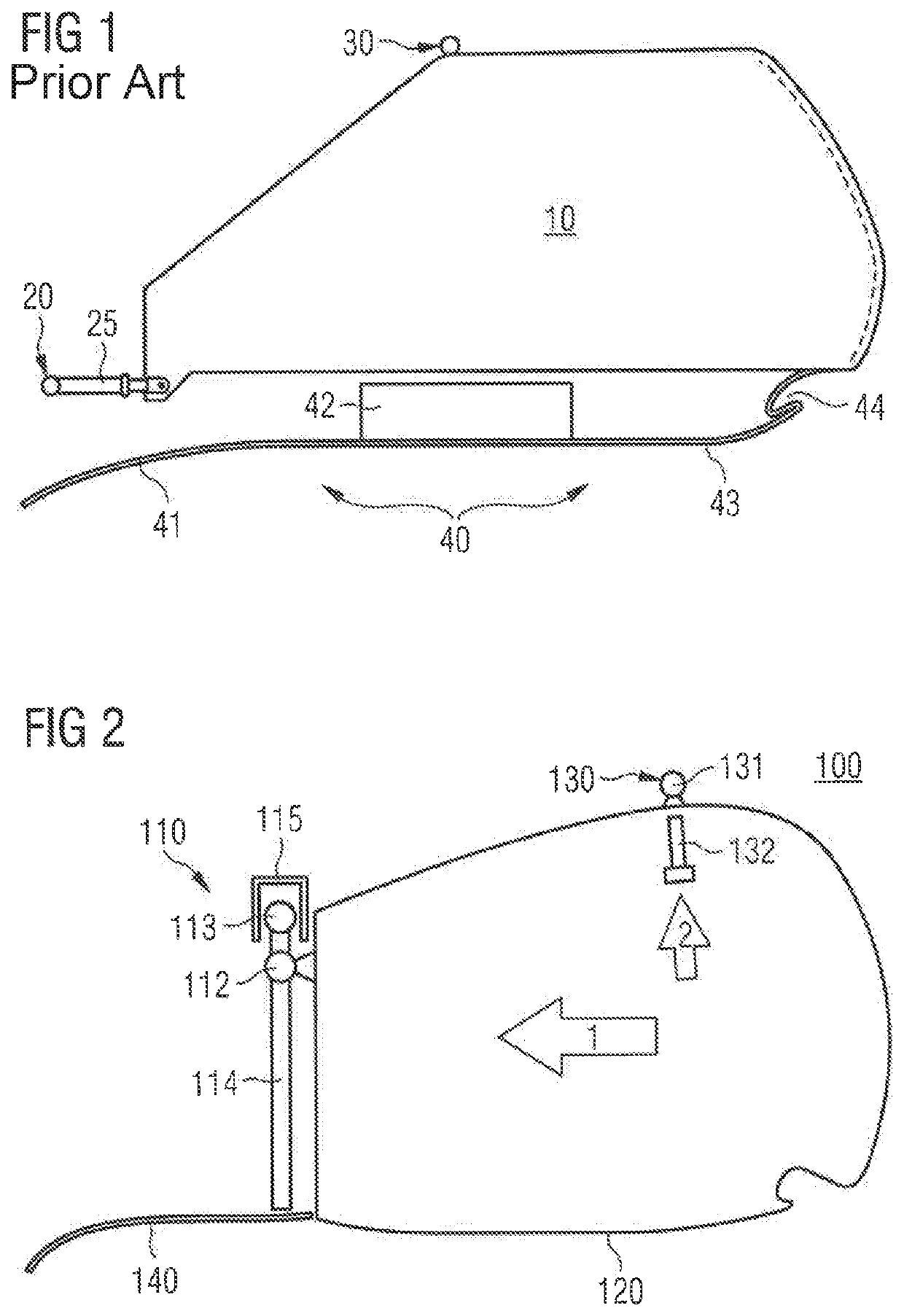
[0053]FIG. 2 shows a cross-sectional overview of an installation system 100. The installation system 100 includes an installation arrangement 110 for connecting a first portion of an overhead luggage compartment 120 and a primary structure fastening element 130 for connecting the second portion of the overhead luggage compartment 120. The overhead luggage compartment 120 can be connected to a primary structure (not shown) of an aircraft. In general, the installation arrangement 110 comprises a first carrier element 112, a second carrier element 113 and a rod 114 (or carrier rod 114). The installation arrangement 110 can be connected to an installation rail 115 via a second carrier element 113. The primary structure fastening element generally includes a primary structure fastening component 131 and the bolt-shaped component 132 to be coupled with the primary structure fastening component 131.

[0054]As is illustrated in FIG. 2 by two arrows, the overhead luggage compartment 120 can be...


PUM


Abstract

An installation arrangement comprising a first carrier element configured to fasten an overhead luggage compartment thereto. The first element includes a main body comprising a tubular opening, a barrel-shaped component arranged inside the tubular opening, the component comprising a through hole extending substantially perpendicular to a component longitudinal axis, and a fastener to fasten a portion of the overhead luggage compartment to the main body of the first carrier element. A second carrier element of the arrangement is a rotary joint connectable to an installation rail, the rotary joint being movable around a longitudinal axis of the installation rail and an axis perpendicular to that longitudinal axis. The installation arrangement also comprises a rod configured to be coupled with the second carrier element and to fit inside the through hole, wherein the rod is connectable to the first carrier element when the rod is arranged inside the through hole.

Description

CROSS-REFERENCES TO RELATED APPLICATIONS[0001]This application claims the benefit of the European patent application No. 16178037.4 filed on Jul. 5, 2016, the entire disclosures of which are incorporated herein by way of reference.BACKGROUND OF THE INVENTION[0002]The present invention relates to an installation arrangement suitable for mounting an overhead luggage compartment in an aircraft and an installation system comprising such an installation arrangement.[0003]An overhead luggage compartment arranged over seat rows in an aircraft is usually attached to a primary structure of the aircraft at at least two positions either directly or via an intermediate structural carrier component. FIG. 1 illustrates a conventional overhead luggage compartment 10 is attached to a primary structure (not shown) at first position 20 and an exemplary second position 30. For instance, installation bars may be affixed to the primary structure of the aircraft at positions 20 and 30 providing attachmen...

Claims


Application Information

Patent Timeline
Patent Type & Authority Patents(United States)
IPC IPC(8): B64D11/00
CPCB64D11/003B64D2011/0046
Inventor BENTHIEN, HERMANNTELKAMP, MICHAEL
Owner AIRBUS OPERATIONS GMBH
Why Eureka
Try Eureka