Modular logic board chassis for a desktop computer
What is AI technical title?
AI technical title is built by Patsnap AI team. It summarizes the technical point description of the patent document.
a logic board and desktop computer technology, applied in the field of chassis for desktop computers, can solve the problems of easy loosening of cables and connectors, and unsightly external cables, etc., and achieve the effect of compact computer devices, high component density, and easy temporary and/or permanent replacemen
Inactive Publication Date: 2005-10-20
APPLE INC
View PDF11 Cites 0 Cited by
Summary
Abstract
Description
Claims
Application Information
AI Technical Summary
This helps you quickly interpret patents by identifying the three key elements:
Problems solved by technology
Method used
Benefits of technology
Benefits of technology
[0013] It is an advantage of the present invention that high component density is achieved, thus allowing a relatively compact computer device.
[0014] It is another advantage of the present invention that chassis connectors are readily accessible, thus providing for the attachment of test equipment, or the like.
[0015] It is a further advantage of the present invention that major components of the computer can be readily temporarily and / or permanently replaced.
[0016] It is yet another advantage of the present invention that a computer can be made to be aesthetically pleasing while maintaining the accessibility of component devices therein.
[0017] These and other objects and advantages of the present invention will become clear to those skilled in the art in view of the description of modes of carrying out the invention, and the industrial applicability thereof, as described herein and as illustrated in the several figures of the drawing. The objects and advantages listed are not an exhaustive list of all possible objects or advantages of the invention. Moreover, it will be possible to practice the invention even where one or more of the intended objects and / or advantages might be absent or not required in the application.
Problems solved by technology
External cables are generally unsightly and provide an additional source off failure in that the cables and connectors readily come loose and / or are damaged as components are moved around.
However, to the inventors' knowledge, no method or apparatus for adequately accomplishing this has existed in the prior art.
Method used
Image
Click on the blue label to locate the original text in one second.
Reading with bidirectional positioning of images and text.
Examples
Embodiment Construction
[0024] The embodiments and variations of the invention described herein, and / or shown in the drawings, are presented by way of example only and are not limiting as to the scope of the invention. Unless otherwise specifically stated, individual aspects and components of the invention may be omitted or modified, or may have substituted therefore known equivalents, or as yet unknown substitutes such as may be developed in the future or such as may be found to be acceptable substitutes in the future. The invention may also be modified for a variety of applications while remaining within the spirit and scope of the claimed invention, since the range of potential applications is great, and since it is intended that the present invention be adaptable to many such variations.
[0025] Unless otherwise stated herein, component parts of the invention will be familiar to one skilled in the art, and may be purchased or readily manufactured accordingly. Also, unless otherwise stated herein, substi...
PUM
Abstract
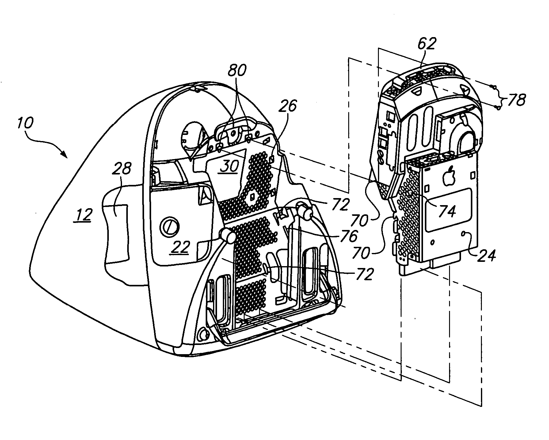
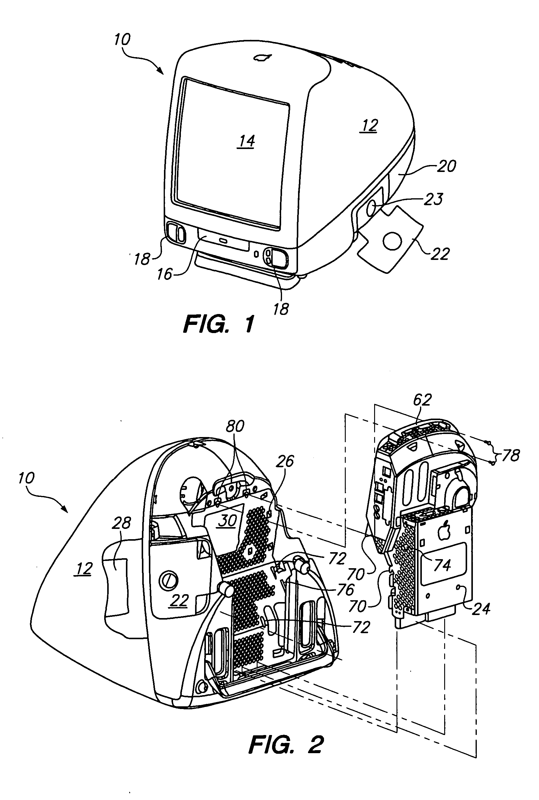
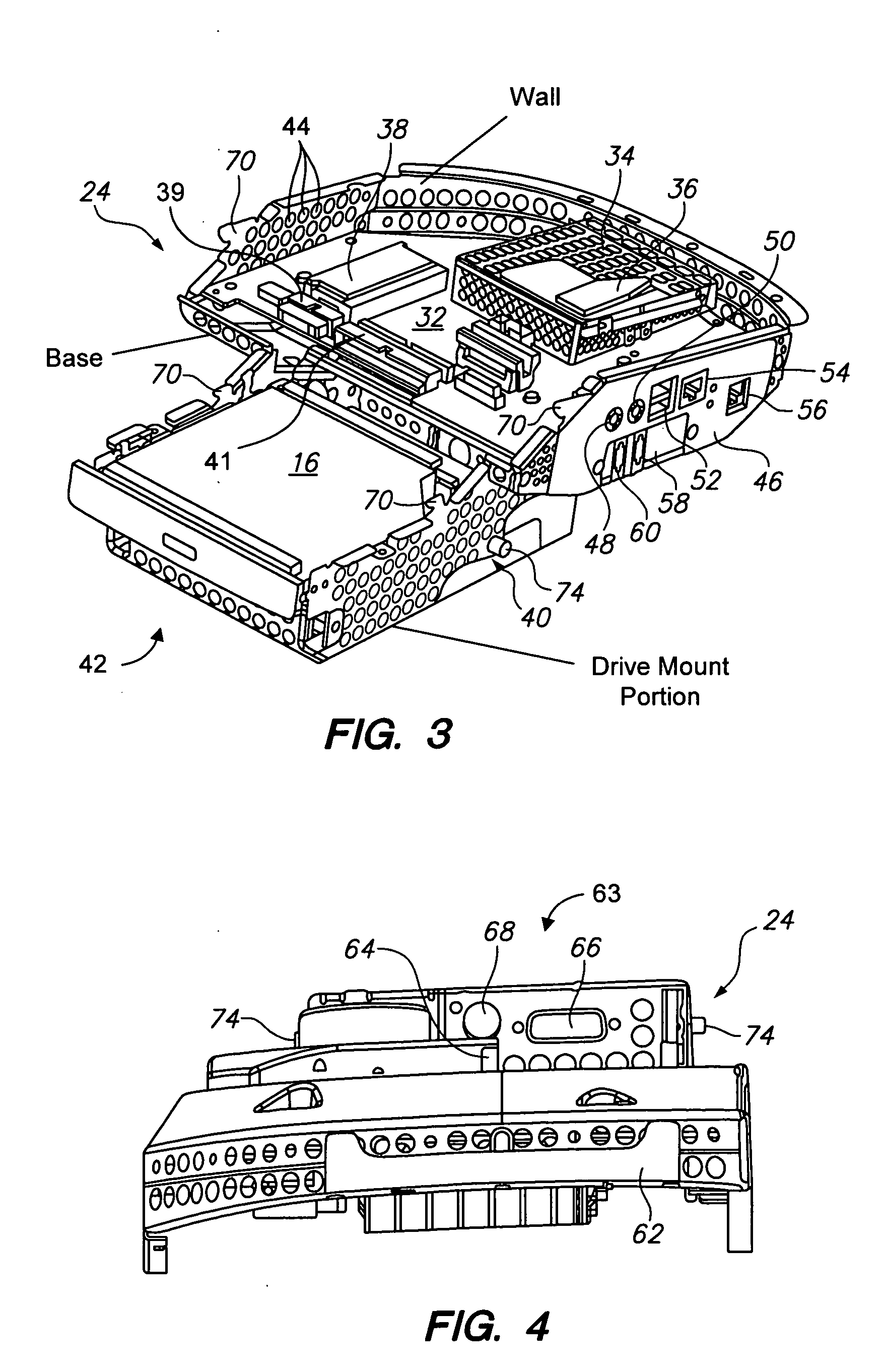
A computer (10) having a monitor housing (12) within which is affixed a logic module (24) having thereon a processor (36), a memory module (38), an internal power connector (39), a fixed disk drive (40), an internal data connector (41), and an external connector panel (46) all generally housed within a sheet metal housing (42) having therein a plurality of perforations (44) for allowing air from a fan assembly (30) to pass therethrough. A power supply (28) and monitor screen (14) are provided in the monitor housing (12) such that when the logic module (24) is mounted and electrically connected within the monitor housing (12) a generally complete computer (10) unit is provided. An auxiliary drive (16) is optionally provided and affixed to the logic module (24) such that the auxiliary drive (16) is externally accessible when the logic module (24) is affixed within the monitor housing (12).
Description
RELATED APPLICATIONS [0001] This application is a continuation of co-pending U.S. patent application Ser. No. 10 / 331,831, filed Dec. 30, 2002, which is a continuation of U.S. patent application Ser. No. 09 / 610,121, filed Jun. 30, 2000, now issued as U.S. Pat. No. 6,519,138, which is a continuation of U.S. patent application Ser. No. 09 / 187,499, filed Nov. 5, 1998, now abandoned, all having at least one inventor in common herewith, and being under obligation of assignment to a common assignee. All parent applications are incorporated herein by reference in their entirety. This application is further related to U.S. patent application Ser. No. 09 / 187,500, filed Nov. 5, 1998, now issued as U.S. Pat. No. 6,216,999, entitled FLOATING MOUNT AND METHOD FOR MOUNTING A DEVICE TO A CHASSIS THEREBY, by David V. Hoenig, Chris J. Novak, Robert N. Olson, and Glen T. Walters, which is incorporated herein by reference in its entirety.TECHNICAL FIELD [0002] The present invention relates to the field...
Claims
Application Information
Patent Timeline
Application Date:The date an application was filed.
Publication Date:The date a patent or application was officially published.
First Publication Date:The earliest publication date of a patent with the same application number.
Issue Date:Publication date of the patent grant document.
PCT Entry Date:The Entry date of PCT National Phase.
Estimated Expiry Date:The statutory expiry date of a patent right according to the Patent Law, and it is the longest term of protection that the patent right can achieve without the termination of the patent right due to other reasons(Term extension factor has been taken into account ).
Invalid Date:Actual expiry date is based on effective date or publication date of legal transaction data of invalid patent.
Patent Type & AuthorityApplications(United States)
IPC IPC(8): G06F1/16G06F1/18
CPCG06F1/1601G06F1/183G06F1/181
InventorOLSON, ROBERT NORMANHOENIG, DAVID V.NOVAK, CHRISTOPHER J.WALTERS, GLEN T.

