Wheel suspension

a technology of suspension and spring, applied in the direction of resilient suspension, interconnection system, vehicle components, etc., can solve the problems of complex structure, high cost, and excessive process time, and achieve the effect of reducing installation costs and sufficient fixing of spring links

Inactive Publication Date: 2010-04-20
FORD GLOBAL TECH LLC
View PDF20 Cites 6 Cited by
  • Summary
  • Abstract
  • Description
  • Claims
  • Application Information

AI Technical Summary

Benefits of technology

[0020]In a further advantageous embodiment of the invention, it is advantageously provided that the bolt has, at its bolt head region, a conical thickening which narrows from the bolt head in the direction of an insertion end of the bolt. In this embodiment, the bolt is pulled with its conical thickening into the bore during the screwing process, so that a conical seat is virtually provided. This is favorable in particular when, in an existing wheel suspension, the existing bolt must be replaced for service or repair reasons. If it is to be additionally possible in the existing wheel suspension for the toe-in to be favorably influenced, it is conceivable for the bolt in its embodiment with the conical thickening to have the abovementioned projection on its bolt head, so that for example a transverse stabilizer can be connected by means of the coupling strut directly to the wheel carrier. In order that the projection can then be mounted in a predefined installation position on the wheel suspension or on the wheel carrier, the bolt can of course also have, in addition to the conical thickening, the flange with the counterstop, which can then interact with the corresponding stop on the connecting element. As a result of the advantageous arrangement of the projection on the bolt head, it is therefore possible to dispense with a separate connection, for example a separate welded connection of a projection, which is formed as an individual part, to the wheel carrier or to its connecting element, in order to connect the coupling strut to the wheel carrier.
[0023]Here, the connecting element is favorably produced in one piece with the wheel carrier, with the two fork limbs being substantially flexible, so that, by means of the force-fitting and form-fitting screw connection, said fork limbs are pulled in the direction of the spring link, which is referred to by way of example and is arranged between the two fork limbs, as a result of which sufficient fixing of the spring link can be obtained. At the same time, the bolt can have the advantageous dual function of for example connecting a transverse stabilizer directly to the wheel carrier via a coupling strut. The connection of the spring link, which is referred to by way of example, to the wheel carrier, and of the transverse stabilizer by means of the coupling strut, is therefore combined in one single component. Installation costs are therefore reduced in comparison to the known prior art, as a result of which a required installation space, with additional material such as for example bolts and nuts, is however also reduced.

Problems solved by technology

A key disadvantage of this known type of wheel suspension involves the connection of the spring link to the wheel carrier by means of the insertion of the bolt and screwing at both sides.
This process is extremely time-consuming and expensive, and requires a multiplicity of components to be used.

Method used


Image

  • Wheel suspension
  • Wheel suspension
  • Wheel suspension

Examples


Embodiment Construction

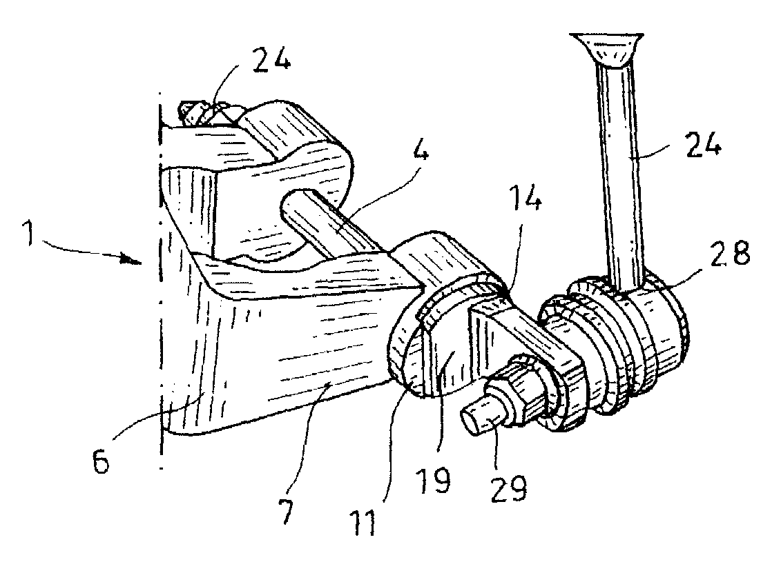
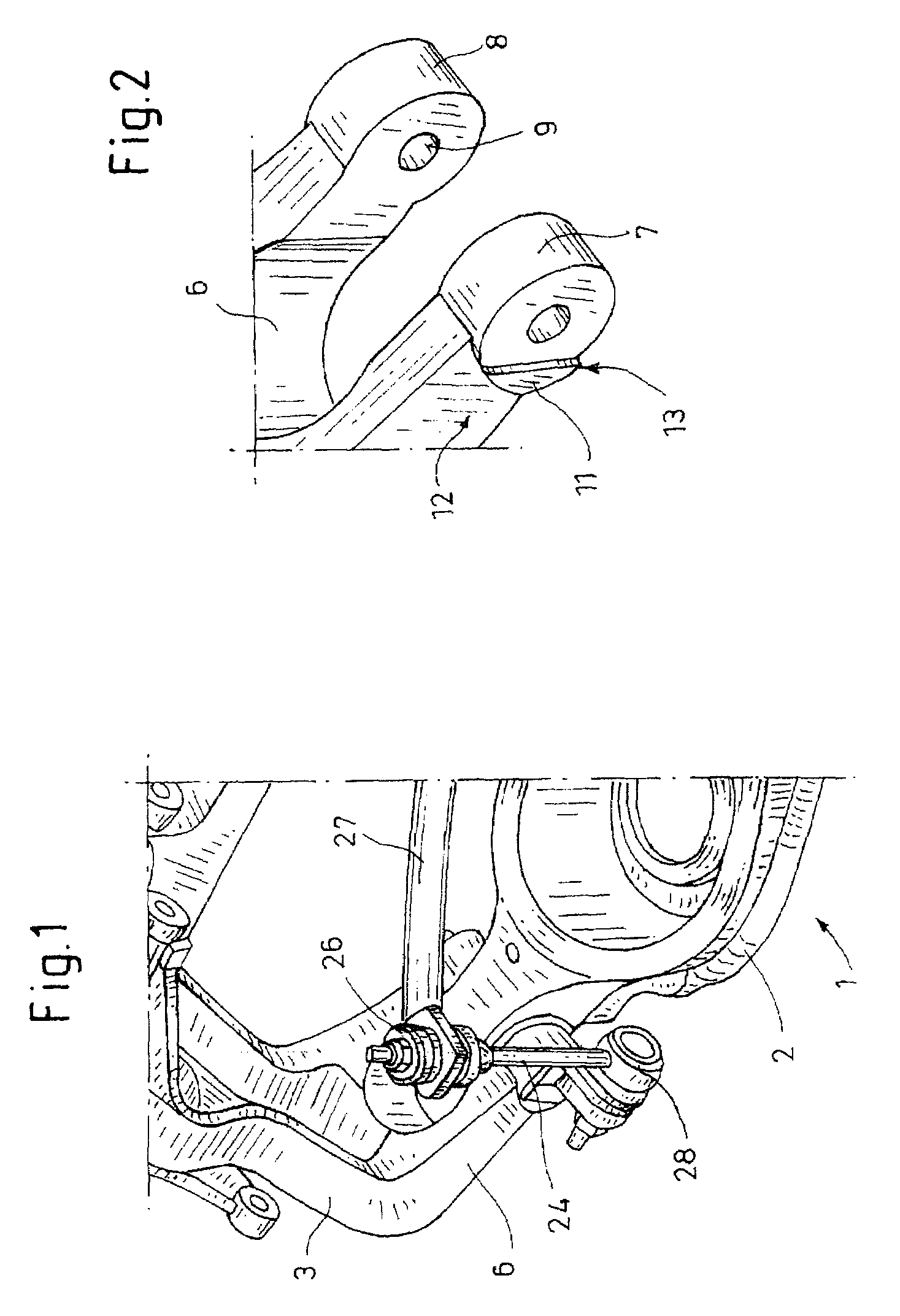
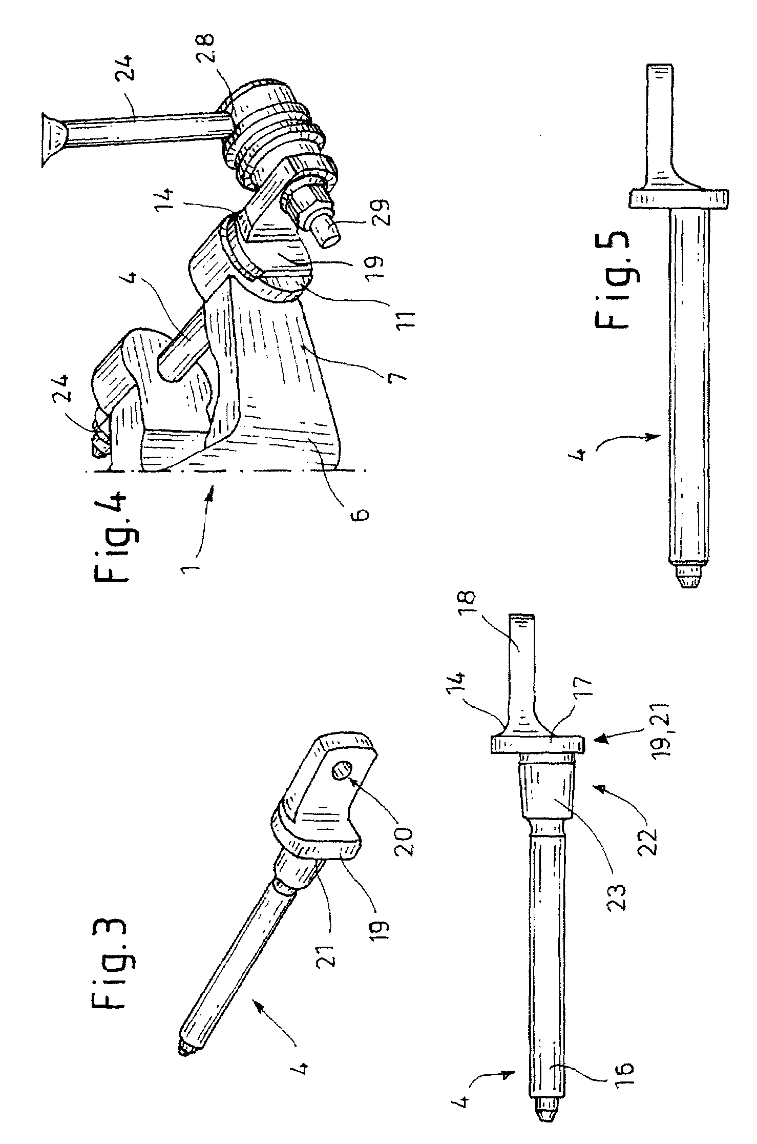
[0031]FIG. 1 shows, by way of example, a wheel suspension 1, which has at least one transverse link 2 and one wheel carrier 3. The wheel carrier 3 has a connecting element 6, through which a bolt 4 (FIG. 4) extends, for connecting to the transverse link 2. The wheel suspension 1 which is illustrated by way of example is a rear wheel suspension of a motor vehicle (not illustrated). Further suspension elements of the wheel suspension 1 are also not shown in FIG. 1 for reasons of clarity.

[0032]In the illustrated exemplary embodiment, the wheel carrier 3 is formed in one piece with the connecting element 6 from a cast part. The wheel carrier 3 can of course be shaped from a metal sheet.

[0033]FIG. 2 shows that the connecting element 6 is of fork-shaped design with two fork limbs 7, 8 in which is formed in each case one bore 9 (FIG. 3) through which the bolt 4 extends.

[0034]On the left-hand fork limb 7 in the drawing plane, the connecting element 6 has a stop 11.

[0035]The stop 11 is forme...


PUM


Abstract

The invention relates to a wheel suspension, which has at least one transverse link and one wheel carrier. The wheel carrier has a connecting element, through which a bolt extends, for connecting to the transverse link. The connecting element has a stop on a limb which is assigned to a bolt head, with the bolt head having a counterstop which corresponds to the stop.

Description

FIELD OF THE INVENTION[0001]The invention relates to a wheel suspension, which has at least one transverse link and one wheel carrier, with the wheel carrier having a connecting element, through which a bolt extends, for connecting to the transverse link.BACKGROUND[0002]Wheel suspensions of are known, with a spring link as a transverse link being connected with its connecting end to the wheel carrier. In this example, the wheel carrier may be a fork-shaped design at its connecting element, with bores being arranged in each of its fork limbs, through which is inserted a threaded bolt. The threaded bolt may project beyond the fork limbs in each instance so that a nut can be screwed onto the projecting free ends, such that the spring link is sufficiently fastened or clamped between the two fork limbs by screwing the nuts onto each projecting free end of the threaded bolt.[0003]A key disadvantage of this known type of wheel suspension involves the connection of the spring link to the wh...

Claims


Application Information

Patent Timeline
Patent Type & Authority Patents(United States)
IPC IPC(8): B60G3/04
CPCB60G7/008B60G21/0551B60G2200/14B60G2206/50B60G2204/148B60G2204/4404B60G2204/1224
Inventor HALFMANN, EDMUNDWESHENDORFF, JORG
Owner FORD GLOBAL TECH LLC
Why Eureka
Try Eureka