Method and apparatus for limiting VSWR spikes in a compact broadband meander line loaded antenna assembly

a broadband meander line and antenna assembly technology, applied in the field of antennas, can solve the problems of large vswr spikes and difficulty in matching, and achieve the effects of reducing vswr spikes, minimizing mismatches, and smoothing out vswr

Inactive Publication Date: 2010-04-20
R A MILLIER IND INC
View PDF12 Cites 5 Cited by
  • Summary
  • Abstract
  • Description
  • Claims
  • Application Information

AI Technical Summary

Benefits of technology

[0012]In the subject invention a meander line of one or more segments is spaced from the associated conductive plate by a lossy dielectric material. This permits inserting a distributed resistance under low impedance sections of the meander line so as to provide the entire meander line structure with the distributed resistance to reduce VSWR spikes without affecting bandwidth. The insertion of this lossy material in essence smoothes out the VSWR by minimizing mismatches.

Problems solved by technology

Such an antenna structure exhibits an anti-resonant point or frequency between the natural resonant frequency fo and 0.5 fo which is very difficult to match.
This anti-resonance is difficult to match and results in large VSWR spikes.

Method used


Image

  • Method and apparatus for limiting VSWR spikes in a compact broadband meander line loaded antenna assembly
  • Method and apparatus for limiting VSWR spikes in a compact broadband meander line loaded antenna assembly
  • Method and apparatus for limiting VSWR spikes in a compact broadband meander line loaded antenna assembly

Examples


Embodiment Construction

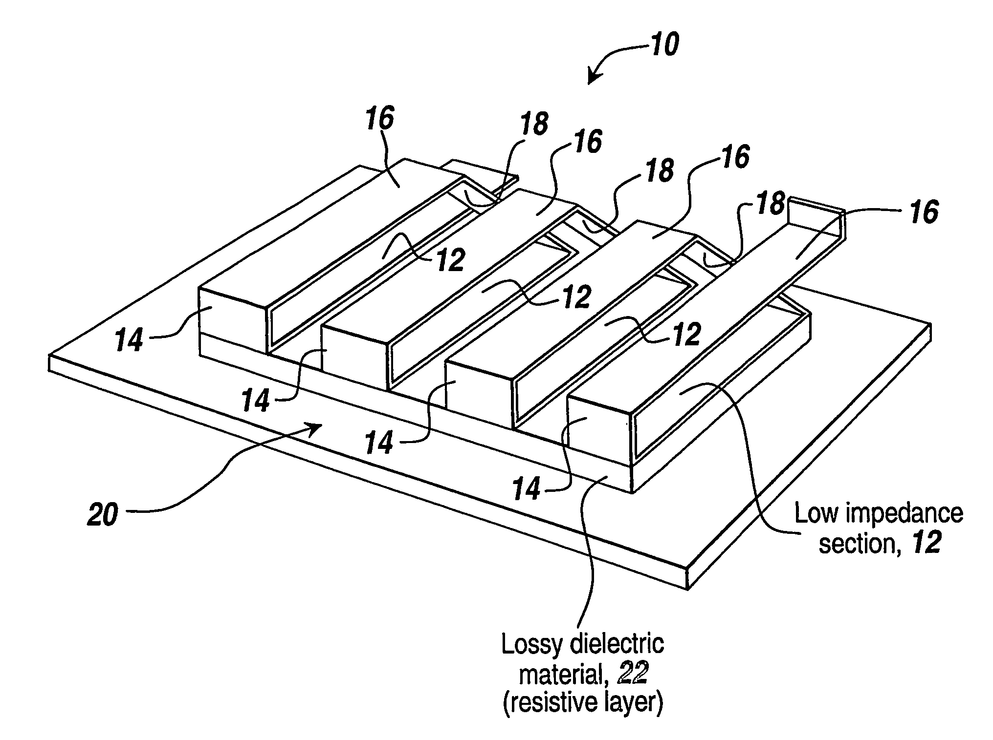
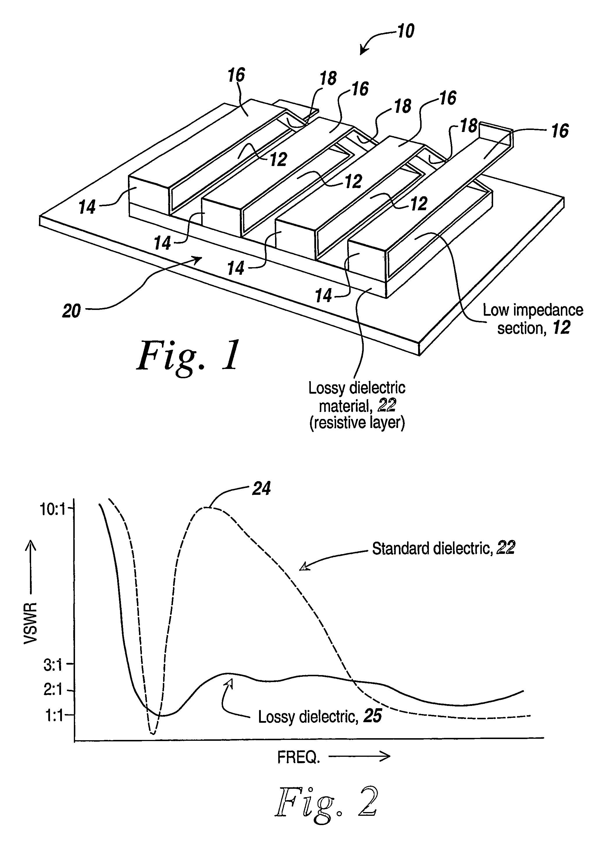
[0024]Referring to FIG. 1, a meander line 10 includes a number of low impedance sections 12 coupled to high impedance sections 14, which are in turn coupled to upper sections 16, with each corresponding to a meander line segment. Note that the segments are serially connected, as can be seen by conductors 18.

[0025]As is typical, the meander line structure is spaced from a conductive plate 20 and in this case by a lossy dielectric material 22, which lies between low impedance sections 12 and plate 20. This lossy dielectric material is in essence a resistive layer and in one embodiment is available from Eccosorb as model VF-30.

[0026]Referring to FIG. 2, one such meander line is formed as part of a meander line loaded antenna. If a standard dielectric is utilized as the layer between the meander line and the conductive plate, then the VSWR curve 22 is occasioned by high VSWR peaks 24 at various frequencies. The result is that at these frequencies there is a substantial impedance mismatc...


PUM


Abstract

A method of operating a higher conductivity broadband loaded meander line antenna (10) is provided wherein the meander line is positioned on a sheet of a lower conductivity material (22) having a conductivity of from about 0.01 siemens / m to about 0.10 siemens / m; and allowing a first electrical current to flow in a first current path in the meander line. An electrical field is formed in the vicinity of the lower conductivity material and a second current flows in a second current path in the lower conductivity material, whereby anti-resonance in the meander line loaded antenna is diminished so that a broadband response can be achieved over bandwidths of 5:1 or more. An assembly for carrying out this method is also disclosed.

Description

STATEMENT OF GOVERNMENT INTEREST[0001]The invention described herein was made under Contract No. MDA 972-00-9-0009 with the Government of the United States of America and may be manufactured and used by and for the Government of the United States of America for Governmental purposes without the payment of any royalties thereon or therefor.FIELD OF THE INVENTION[0002]The present invention relates to antennas and more particularly to broadband meander line antennas.BACKGROUND OF THE INVENTION[0003]Modern military communication systems require antennas that are small, broadband and have good gain. It is difficult to make electrically small antennas (i.e. less than ¼-wavelength in maximum linear dimension) broadband without seriously impacting gain performance.[0004]One widely used method of making an electrically small antenna broadband is to add a resistive taper along the length of the antenna. This taper is usually determined empirically. More recently, people have applied genetic a...

Claims


Application Information

Patent Timeline
Patent Type & Authority Patents(United States)
IPC IPC(8): H01Q11/12H01Q1/36H01Q1/38H01Q11/08
CPCH01Q1/36H01Q1/362H01Q11/08H01Q9/42H01Q1/38
Inventor MCKIVERGAN, PATRICK D.
Owner R A MILLIER IND INC
Why Eureka
Try Eureka