
1911 Handgun bushing tool

a technology for handguns and wrenches, which is applied in the direction of weapons, weapon components, etc., can solve the problems of loss of parts, lack of flat surface for barrel bushing tools or wrenches, and inability to provide a flat surface large enough to protect users

Inactive Publication Date: 2010-04-27
JOHNS JEFFREY BRYAN
View PDF8 Cites 12 Cited by
  • Summary
  • Abstract
  • Description
  • Claims
  • Application Information

AI Technical Summary

Benefits of technology

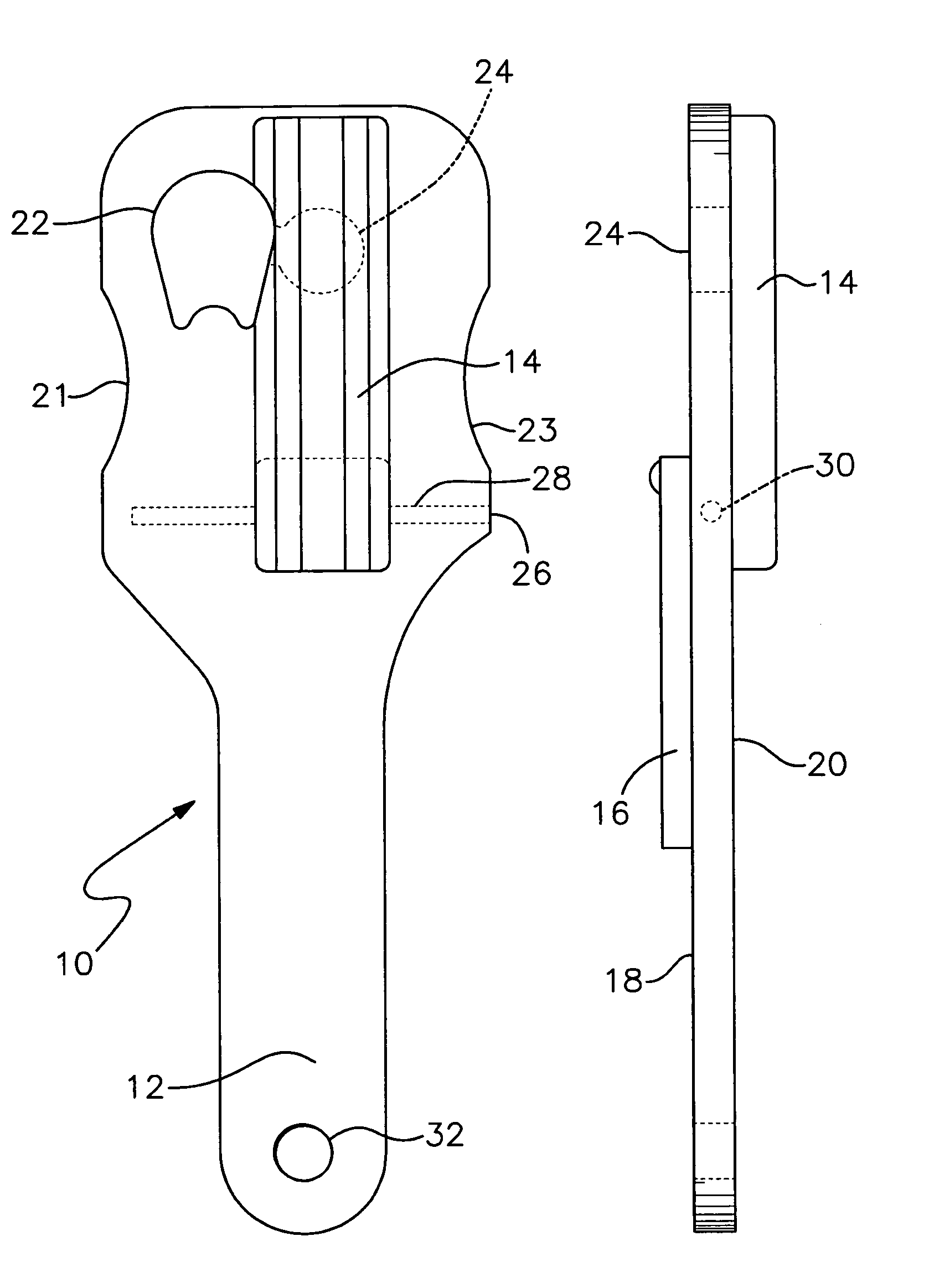
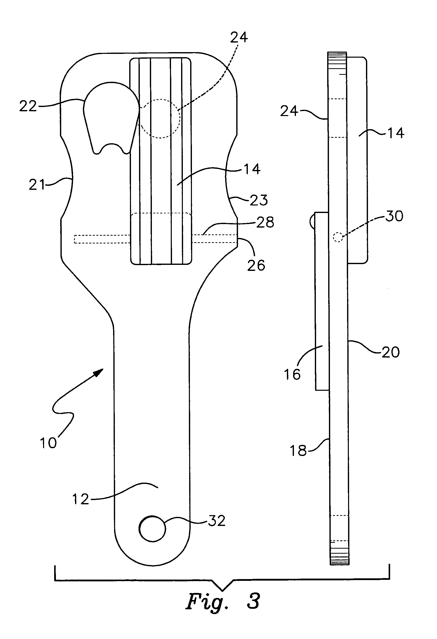
"The invention is a tool designed to safely disassemble and assemble the barrel bushing, recoil spring, and recoil spring plug on a Model (1911, 1911A1, or 2011) semiautomatic handgun. The tool is strong, long-handled, and has a simple lever system that allows for easy assembly and disassembly of the barrel bushing and recoil spring plug. The tool also has interchangeable inserts that fit different manufacturer's designs and a removable insert for replacement after prolonged use and wear. The tool is efficient, fast-operating, and can be used by both right and left-handed personnel. It is meant for harsh environments and can withstand extreme pressures without failure or breakage."

Problems solved by technology

When the barrel bushing is rotated under spring pressure, caution must be observed as the recoil spring plug and spring may fly out of the slide causing injury or loss of the parts or both.
Previously constructed barrel bushing tools are normally made from a flat stamped out sheet of metal or by injection molding from plastics or polymers and do not incorporate a mechanism for safely trapping and capturing the recoil spring or recoil spring plug for disassembly or assembly.
Previously constructed barrel bushing tools or wrenches do not provide a flat surface large enough to protect the user from a flying recoil spring or recoil spring plug.
Previously constructed barrel bushing tools or wrenches do not have replaceable inserts for differently designed bushing.
Previously constructed barrel bushing tools do not have replaceable inserts to allow for wear and long term use.
Previously constructed barrel bushing tools were made of soft materials and easily broken.
Previously constructed barrel bushing tools were not manufactured to tight tolerances and in some cases did not fit the barrel bushing to allow for rotation.

Method used


Image

  • 1911 Handgun bushing tool
  • 1911 Handgun bushing tool
  • 1911 Handgun bushing tool

Examples


Embodiment Construction

[0042]Detailed descriptions of the preferred embodiment are provided herein. It is to be understood, however, that the present invention may be embodied in various forms. Therefore, specific details disclosed herein are not to be interpreted as limiting, but rather as a basis for the claims and as a representative basis for teaching one skilled in the art to employ the present invention in virtually any appropriately detailed system, structure or manner.

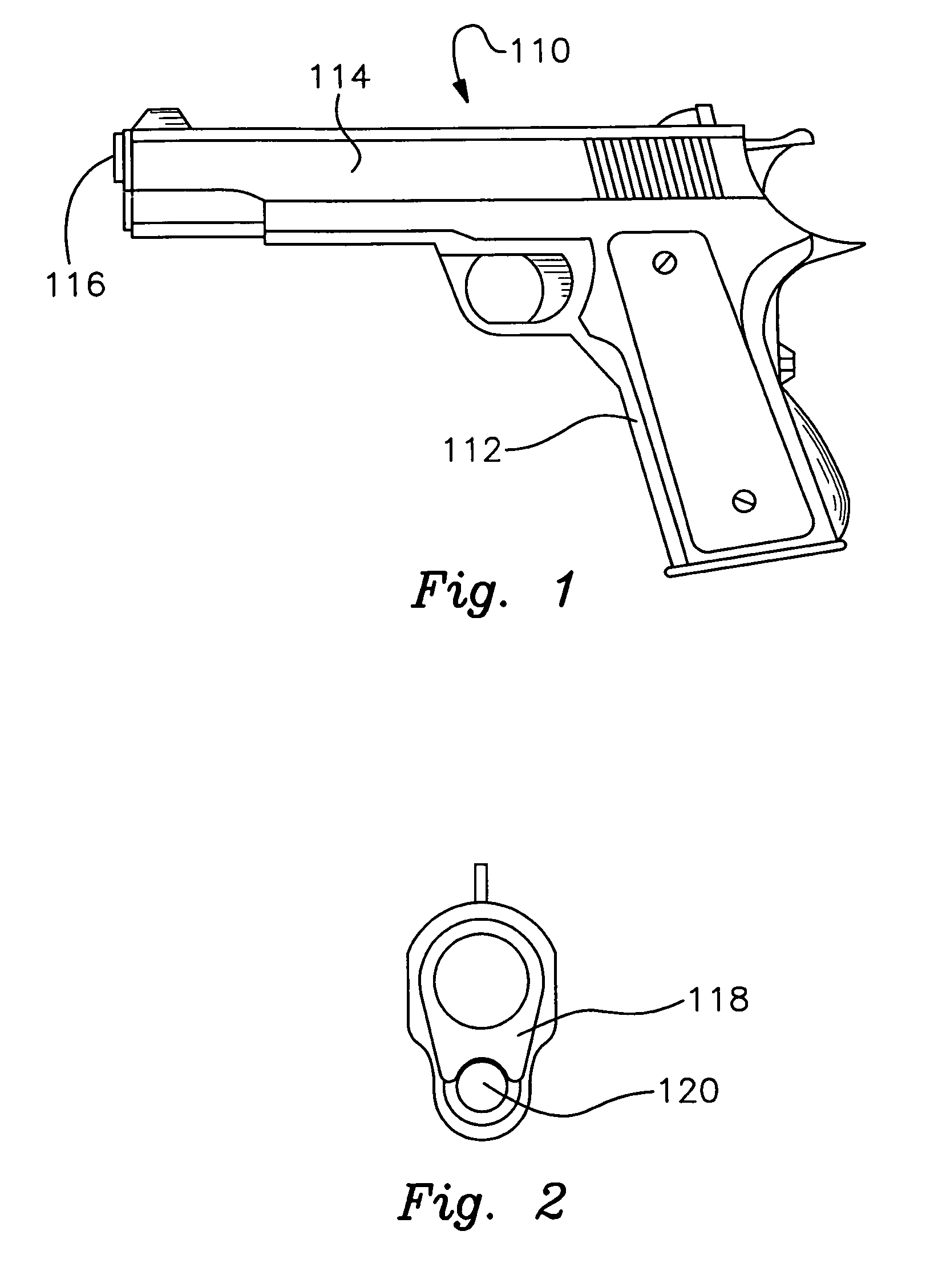
[0043]Turning first to FIG. 1, there is shown an elemental side and front view elevation of a prior art U.S. caliber 0.45 model 911 semi-automatic firearm or pistol;

[0044]Turning to FIG. 2, there is shown an elemental front view elevation of a prior art U.S. caliber 0.45 model 1911 semi-automatic firearm or pistol with a standard rotating barrel bushing;

[0045]Next, turning to FIGS. 3 through 9;

[0046]FIG. 3 is a detailed top view with rotated side view of the tool of the present invention showing the placement of the lever and handle ...


PUM


Abstract

A handgun bushing tool to facilitate the safe removal and replacement of a barrel bushing on a handgun such as a Model 1911, 1911-A1, 2011 type semiautomatic pistol using a single stack or staggered double-column magazine and having a barrel that requires a bushing and recoil spring plug to secure it. The tool has a handle with an aperture conforming to the shape of a barrel bushing; a hole conforming to the shape of a recoil spring plug and a lever assembly with a reversible handle that allows for pressure to be placed on the recoil spring and plug during the disassembly and assembly process. The tool also incorporate an alternate cutout in the handle which allows for a removable insert to be placed in the handle so as to allow for inserts of different types to accommodate differently shaped bushings made by a number of different manufacturers.

Description

CROSS REFERENCE TO RELATED APPLICATIONS[0001]This is a continuation of Ser. No. 60 / 858,467, filed on Nov. 13, 2006.STATEMENT REGARDING FEDERALLY SPONSORED RESEARCH OR DEVELOPMENT[0002]Not ApplicableDESCRIPTION OF ATTACHED APPENDIX[0003]Not ApplicableBACKGROUND OF THE INVENTION[0004]The present invention relates to a handgun tool, and more particularly, to a barrel bushing removal and installation tool for a semiautomatic handgun.[0005]A semiautomatic handgun developed for the U.S. Army in 1911 is often referred to as a Model 1911. This handgun was extremely well designed to operate in adverse environments and fire with great accuracy projectiles having high kinetic energy at point of impact. Numerous variations have been developed over the years, both in details of construction and with calibers different from the initial 0.45 caliber bore.[0006]One popular variant is known as the Model 1911-A1. This variant uses a single column magazine in which the rounds are stacked linearly on t...

Claims


Application Information

Patent Timeline
Patent Type & Authority Patents(United States)
IPC IPC(8): F41A99/00
CPCF41A21/00
Inventor JOHNS, JEFFREY BRYAN
Owner JOHNS JEFFREY BRYAN
Learn More