
Heavy duty reclining mechanism for vehicle seats

a reclining mechanism and vehicle seat technology, applied in the direction of vehicle seats, vehicle components, movable seats, etc., can solve the problems of laborious and complicated assembly of the reclining mechanism, the axial thickness of the prior art reclining mechanism in some instances exceeding the space available between the seat base and the seat back,

Active Publication Date: 2010-04-27
LEAR CORP
View PDF42 Cites 37 Cited by
  • Summary
  • Abstract
  • Description
  • Claims
  • Application Information

AI Technical Summary

Benefits of technology

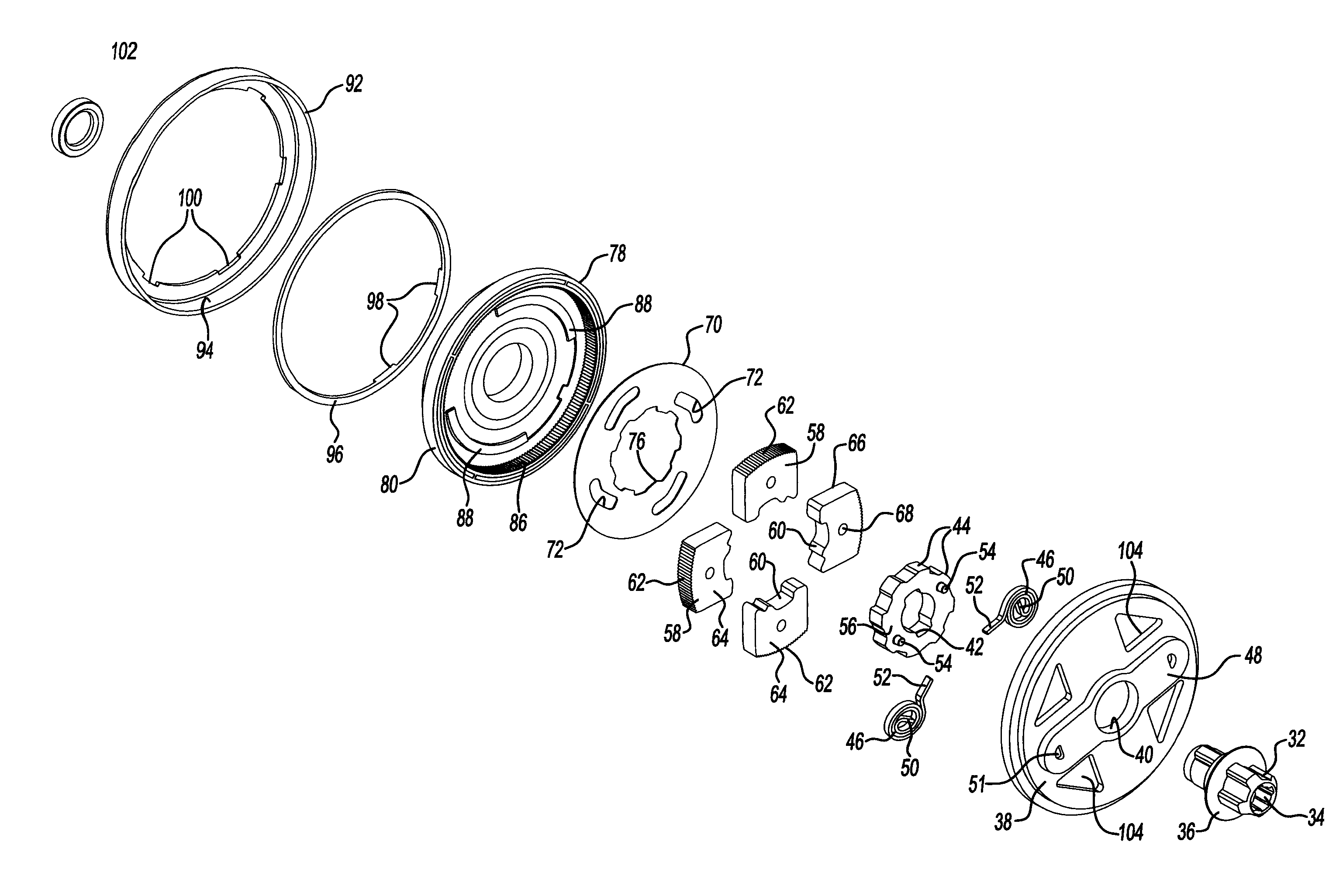
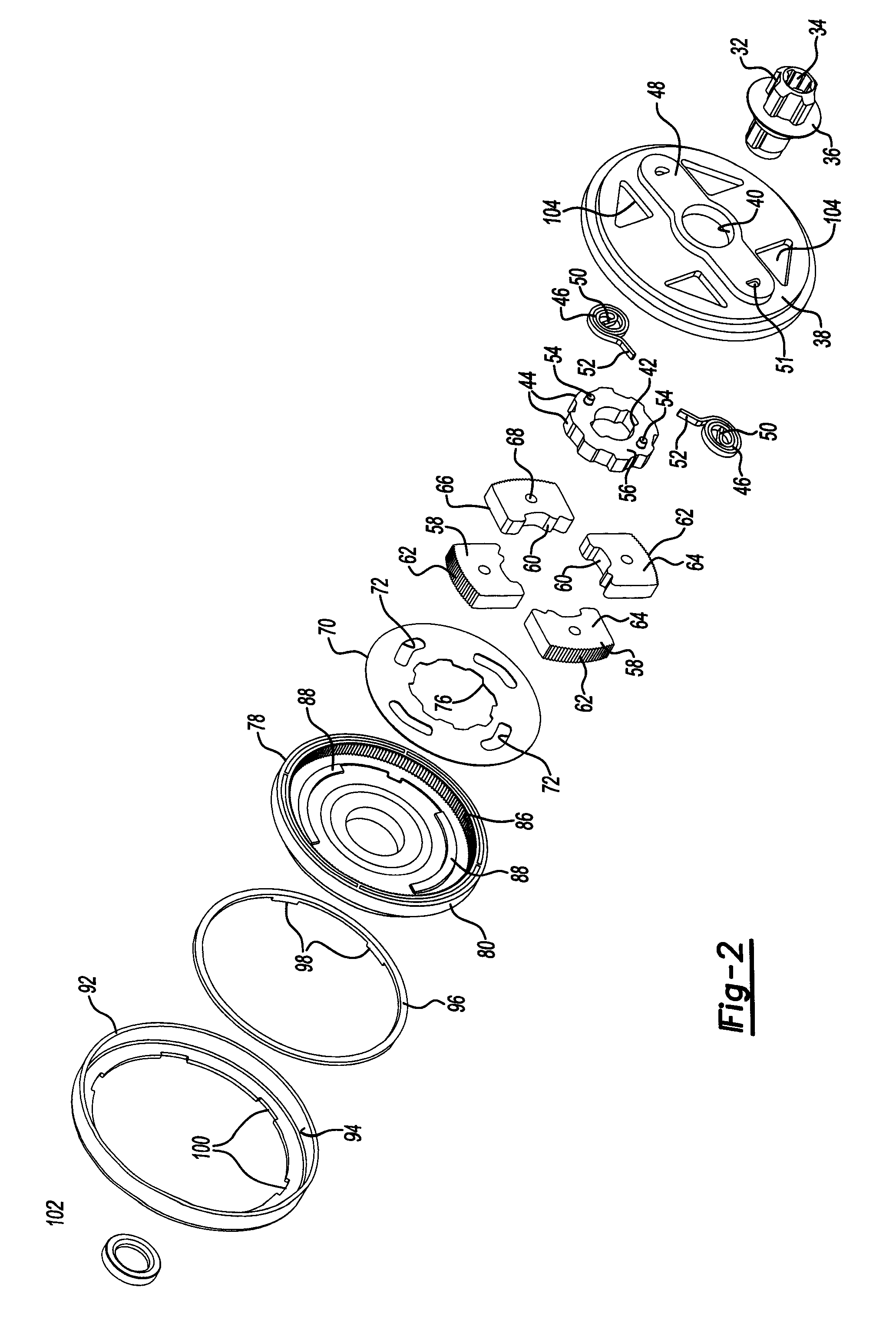
The invention is a reclining mechanism for a vehicle seat that includes a guide plate and a pivotal plate connected by a pivot. The mechanism has a cam with internal gear teeth and a hub with external gear teeth that engage with the internal gear teeth. The locking elements have gear teeth that engage with the internal gear teeth and are moved between a locked position and an unlocked position. The mechanism also includes springs that bias the cam and a control plate that engages the locking elements. The invention also includes an arcuate rib that prevents the locking elements from returning to the locked position and a clamping ring that locates the pivotal plate relative to the guide plate. The technical effects of the invention include improved locking mechanisms, reduced noise and improved comfort for the occupant.

Problems solved by technology

The components of prior art reclining mechanisms are not easily assembled into a compact package.
The axial thickness of prior art reclining mechanisms in some instances exceeded the space available between the seat base and seat back.
Assembly of the reclining mechanism can be complicated and labor intensive.
The need to assemble spring biased parts together may tend to complicate assembly processes because of the need to compress the spring as parts are assembled together in some designs.

Method used


Image

  • Heavy duty reclining mechanism for vehicle seats
  • Heavy duty reclining mechanism for vehicle seats
  • Heavy duty reclining mechanism for vehicle seats

Examples


Embodiment Construction

[0021]An illustrated embodiment of the invention is disclosed below but it is to be understood that the disclosed embodiments are merely examples of the invention that may be embodied in various and alternative forms. The figures are not necessarily to scale and some features may be exaggerated or minimized to show details of particular components. The specific structural and functional details are not to be interpreted as limiting, but merely as a representative embodiment providing support for the claims and are intended to be sufficient to teach one skilled in the art how to practice the invention.

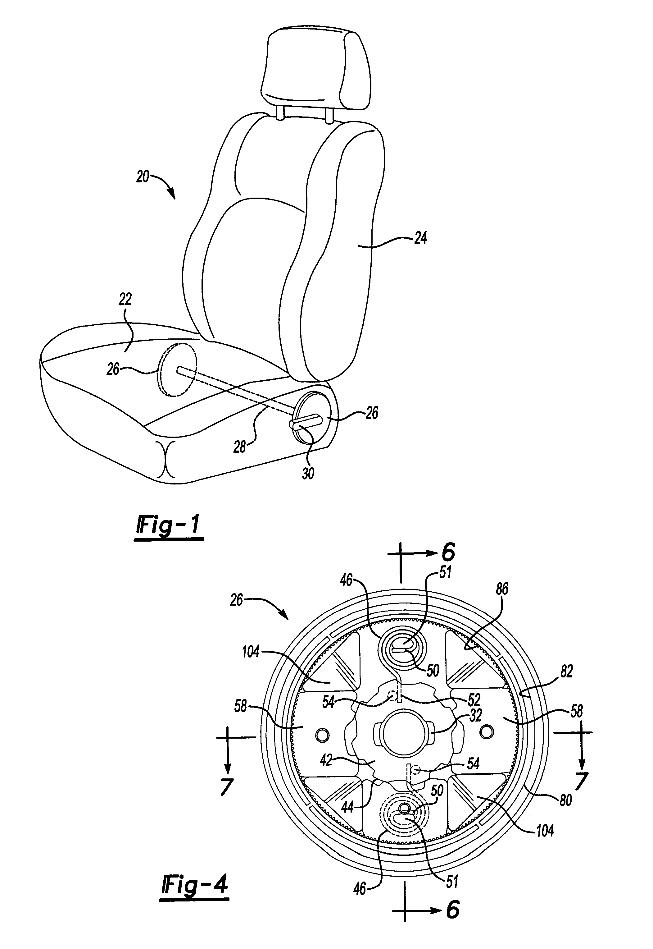
[0022]Referring now to FIG. 1, a seat assembly is illustrated and referenced generally by numeral 20. The seat assembly 20 includes a horizontal seat base 22. The seat assembly 20 also includes an upright seat back 24. A pair of reclining mechanisms 26 connect the seat base 22 to the seat back 24. The reclining mechanisms 26 are connected together by a shaft 28. The shaft 28 links the r...


PUM


Abstract

A manual vehicle seat reclining mechanism and seat assembly incorporating the reclining mechanism is disclosed. A guide plate and a pivotal plate are assembled together and disposed between the seat base and seat back. A cam is biased by a spring to hold locking elements in engagement with the pivotal plate. A control plate is manually rotated with the cam to release the locking elements by drawing pins on one side of the locking plates radially inwardly with slots provided in the control plate. Ribs are provided on the pivotal plate that prevent the locking elements from returning to the locked position in certain radial alignments of the pivotal plate relative to the guide plate.

Description

BACKGROUND OF THE INVENTION[0001]1. Field of the Invention[0002]The invention relates to reclining mechanisms for vehicle seating assemblies, more specifically to heavy duty manually operated reclining mechanisms.[0003]2. Background Art[0004]Vehicle seats generally include a seat base and a seat back. Reclining mechanisms for vehicle seats allow the seats to be positioned to accommodate different body types and the personal comfort of seat occupants. Reclining mechanisms for vehicle seats permit the seat back to pivot to allow a passenger to recline or incline the seat.[0005]Manually operated reclining mechanisms establish a locked position in which the seat back does not pivot and an unlocked position in which the seat back can pivot. The mechanism is switched between a locked position and an unlocked position when a user manually operates the reclining mechanism. The mechanism is returned to the normally locked position after the user adjusts the reclining mechanism. Full engageme...

Claims


Application Information

Patent Timeline
Patent Type & Authority Patents(United States)
IPC IPC(8): B60N2/02
CPCB60N2/2356B60N2/236
Inventor WAHLS, ROBERTWAWRZYNIAK, JAMES S.
Owner LEAR CORP
Learn More